HP 550 HP 550 Notebook PC - Maintenance and Service Guide - Page 54
Switch cover, that secure the optical drive bracket to the optical
 |
View all HP 550 manuals
Add to My Manuals
Save this manual to your list of manuals |
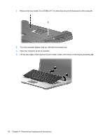
Page 54 highlights
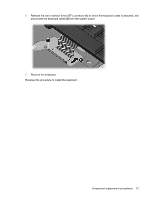
4. Remove the optical drive (3) from the computer. 5. If it is necessary to replace the optical drive bracket, position the optical drive with the rear toward you. 6. Remove the two Phillips PM2.0×4.0 screws (1) that secure the optical drive bracket to the optical drive. 7. Remove the optical drive bracket (2). Reverse this procedure to reassemble and install an optical drive. Switch cover Description Switch cover (includes button board and cable) Spare part number 495388-001 46 Chapter 4 Removal and replacement procedures
-
 1
1 -
2
-
3
-
4
-
5
-
6
-
7
-
8
-
9
-
10
-
11
-
12
-
13
-
14
-
15
-
16
-
17
-
18
-
19
-
20
-
21
-
22
-
23
-
24
-
25
-
26
-
27
-
28
-
29
-
30
-
31
-
32
-
33
-
34
-
35
-
36
-
37
-
38
-
39
-
40
-
41
-
42
-
43
-
44
-
45
-
46
-
47
-
48
-
 49
49 -
 50
50 -
 51
51 -
 52
52 -
 53
53 -
 54
54 -
 55
55 -
 56
56 -
 57
57 -
 58
58 -
 59
59 -
60
-
61
-
62
-
63
-
64
-
65
-
66
-
67
-
68
-
69
-
70
-
71
-
72
-
73
-
74
-
75
-
76
-
77
-
78
-
79
-
80
-
81
-
82
-
83
-
84
-
85
-
86
-
87
-
88
-
89
-
90
-
91
-
92
-
93
-
94
-
95
-
96
-
97
-
98
-
99
-
100
-
101
-
102
-
103
-
104
-
105
-
106
-
107
-
108
-
109
-
110
-
111
-
112
-
113
-
114
-
115
-
116
-
117
-
118
-
119
-
120
-
121
-
122
-
123
-
124
-
125
-
126
-
127
-
128
-
129
-
130
-
131
-
132
-
133
-
134
-
135
-
136
-
137
-
138
-
139
-
140
-
141
-
142
-
143
-
144
-
145
-
146
-
147
-
148
 |
 |
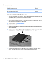
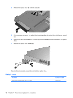
4.
Remove the optical drive
(3)
from the computer.
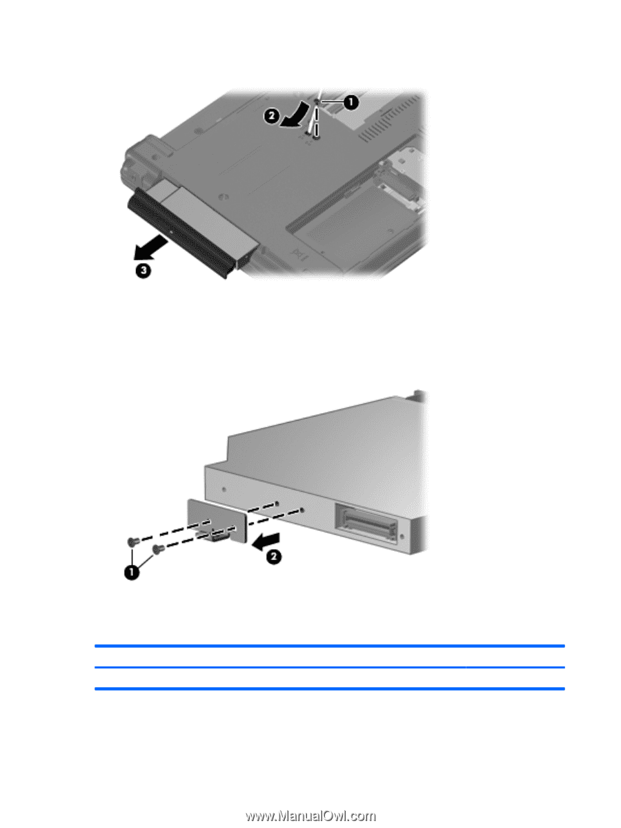
5.
If it is necessary to replace the optical drive bracket, position the optical drive with the rear toward
you.
6.
Remove the two Phillips PM2.0×4.0 screws
(1)
that secure the optical drive bracket to the optical
drive.
7.
Remove the optical drive bracket
(2)
.
Reverse this procedure to reassemble and install an optical drive.
Switch cover
Description
Spare part number
Switch cover (includes button board and cable)
495388-001
46
Chapter 4
Removal and replacement procedures