HP 550 HP 550 Notebook PC - Maintenance and Service Guide - Page 63
CAUTION, the display assembly can result in damage to the display assembly and other computer
 |
View all HP 550 manuals
Add to My Manuals
Save this manual to your list of manuals |
Page 63 highlights
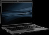
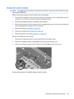
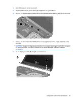
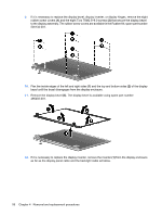
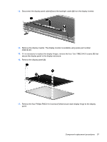
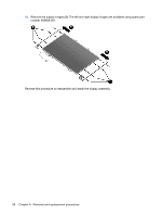
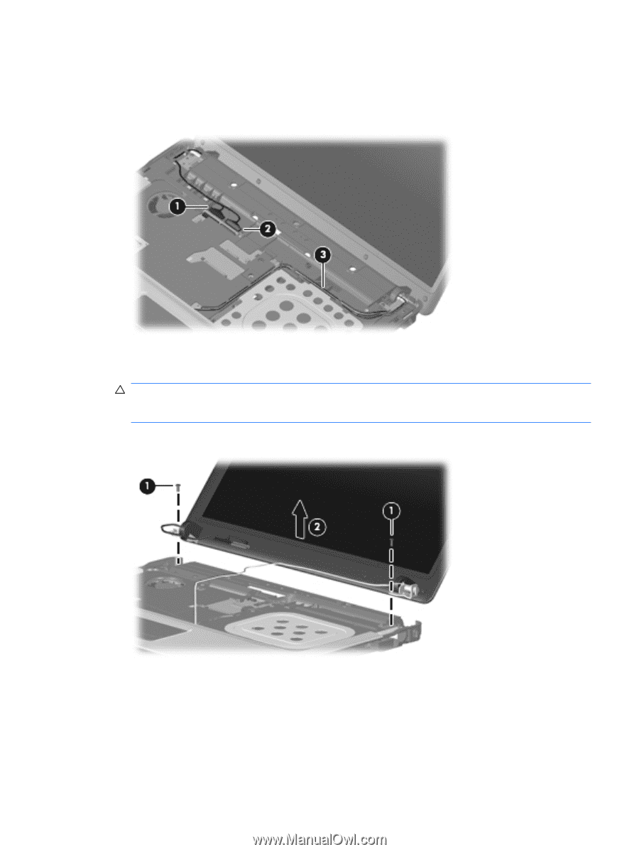
4. Open the computer as far as possible. 5. Disconnect the display panel cables (1) and (2) from the system board. 6. Remove the wireless antenna cables (3) from the clips and routing channels built into the top cover. 7. Remove the four slotted Torx ST8M2.5×7.0 screws (1) that secure the display assembly to the computer. CAUTION: Support the display assembly when removing the following screws. Failure to support the display assembly can result in damage to the display assembly and other computer components. 8. Lift the display assembly (2) straight up and remove it. Component replacement procedures 55
-
 1
1 -
2
-
3
-
4
-
5
-
6
-
7
-
8
-
9
-
10
-
11
-
12
-
13
-
14
-
15
-
16
-
17
-
18
-
19
-
20
-
21
-
22
-
23
-
24
-
25
-
26
-
27
-
28
-
29
-
30
-
31
-
32
-
33
-
34
-
35
-
36
-
37
-
38
-
39
-
40
-
41
-
42
-
43
-
44
-
45
-
46
-
47
-
48
-
49
-
50
-
51
-
52
-
53
-
54
-
55
-
56
-
57
-
 58
58 -
 59
59 -
 60
60 -
 61
61 -
 62
62 -
 63
63 -
 64
64 -
 65
65 -
 66
66 -
 67
67 -
 68
68 -
69
-
70
-
71
-
72
-
73
-
74
-
75
-
76
-
77
-
78
-
79
-
80
-
81
-
82
-
83
-
84
-
85
-
86
-
87
-
88
-
89
-
90
-
91
-
92
-
93
-
94
-
95
-
96
-
97
-
98
-
99
-
100
-
101
-
102
-
103
-
104
-
105
-
106
-
107
-
108
-
109
-
110
-
111
-
112
-
113
-
114
-
115
-
116
-
117
-
118
-
119
-
120
-
121
-
122
-
123
-
124
-
125
-
126
-
127
-
128
-
129
-
130
-
131
-
132
-
133
-
134
-
135
-
136
-
137
-
138
-
139
-
140
-
141
-
142
-
143
-
144
-
145
-
146
-
147
-
148
 |
 |
4.
Open the computer as far as possible.
5.
Disconnect the display panel cables
(1)
and
(2)
from the system board.
6.
Remove the wireless antenna cables
(3)
from the clips and routing channels built into the top cover.
7.
Remove the four slotted Torx ST8M2.5×7.0 screws
(1)
that secure the display assembly to the
computer.
CAUTION:
Support the display assembly when removing the following screws. Failure to support
the display assembly can result in damage to the display assembly and other computer
components.
8.
Lift the display assembly
(2)
straight up and remove it.
Component replacement procedures
55