HP 550 HP 550 Notebook PC - Maintenance and Service Guide - Page 65
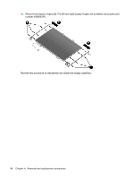
Remove the display panel, Remove the four Phillips PM2.0×4.0 screws
 |
View all HP 550 manuals
Add to My Manuals
Save this manual to your list of manuals |
Page 65 highlights
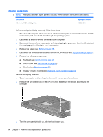
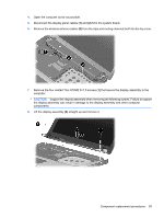
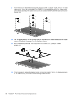
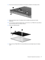
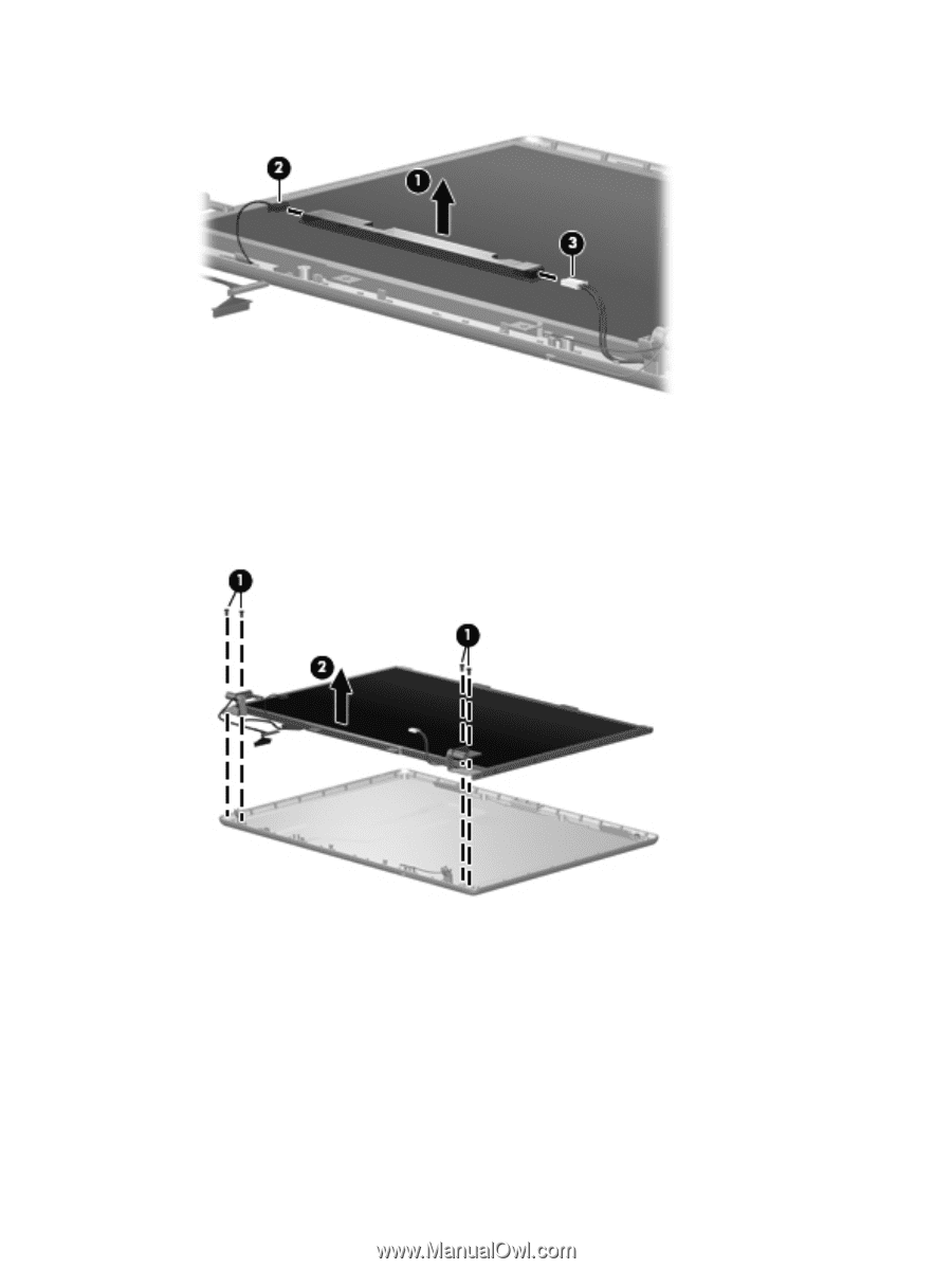
13. Disconnect the display panel cable (2) and the backlight cable (3) from the display inverter. 14. Remove the display inverter. The display inverter is available using spare part number 456618-001. 15. If it is necessary to replace the display hinges, remove the four Torx T8M2.5×6.0 screws (1) that secure the display panel to the display enclosure. 16. Remove the display panel (2). 17. Remove the four Phillips PM2.0×4.0 screws (1) that secure each display hinge to the display panel. Component replacement procedures 57
-
 1
1 -
2
-
3
-
4
-
5
-
6
-
7
-
8
-
9
-
10
-
11
-
12
-
13
-
14
-
15
-
16
-
17
-
18
-
19
-
20
-
21
-
22
-
23
-
24
-
25
-
26
-
27
-
28
-
29
-
30
-
31
-
32
-
33
-
34
-
35
-
36
-
37
-
38
-
39
-
40
-
41
-
42
-
43
-
44
-
45
-
46
-
47
-
48
-
49
-
50
-
51
-
52
-
53
-
54
-
55
-
56
-
57
-
58
-
59
-
 60
60 -
 61
61 -
 62
62 -
 63
63 -
 64
64 -
 65
65 -
 66
66 -
 67
67 -
 68
68 -
 69
69 -
 70
70 -
71
-
72
-
73
-
74
-
75
-
76
-
77
-
78
-
79
-
80
-
81
-
82
-
83
-
84
-
85
-
86
-
87
-
88
-
89
-
90
-
91
-
92
-
93
-
94
-
95
-
96
-
97
-
98
-
99
-
100
-
101
-
102
-
103
-
104
-
105
-
106
-
107
-
108
-
109
-
110
-
111
-
112
-
113
-
114
-
115
-
116
-
117
-
118
-
119
-
120
-
121
-
122
-
123
-
124
-
125
-
126
-
127
-
128
-
129
-
130
-
131
-
132
-
133
-
134
-
135
-
136
-
137
-
138
-
139
-
140
-
141
-
142
-
143
-
144
-
145
-
146
-
147
-
148
 |
 |
13.
Disconnect the display panel cable
(2)
and the backlight cable
(3)
from the display inverter.
14.
Remove the display inverter. The display inverter is available using spare part number
456618-001.
15.
If it is necessary to replace the display hinges, remove the four Torx T8M2.5×6.0 screws
(1)
that
secure the display panel to the display enclosure.
16.
Remove the display panel
(2)
.
17.
Remove the four Phillips PM2.0×4.0 screws
(1)
that secure each display hinge to the display
panel.
Component replacement procedures
57