HP 600 HP StorageWorks 600 Modular Disk System Maintenance and Service Guide
HP 600 Manual
 |
View all HP 600 manuals
Add to My Manuals
Save this manual to your list of manuals |
HP 600 manual content summary:
- HP 600 | HP StorageWorks 600 Modular Disk System Maintenance and Service Guide - Page 1
HP StorageWorks 600 Modular Disk System Maintenance and Service Guide Abstract This guide describes identification and maintenance procedures, diagnostic tools, specifications and requirements for hardware components and software. This guide is for an experienced service technician. HP assumes you - HP 600 | HP StorageWorks 600 Modular Disk System Maintenance and Service Guide - Page 2
to change without notice. The only warranties for HP products and services are set forth in the express warranty statements accompanying such products and services. Nothing herein should be construed as constituting an additional warranty. HP shall not be liable for technical or editorial errors - HP 600 | HP StorageWorks 600 Modular Disk System Maintenance and Service Guide - Page 3
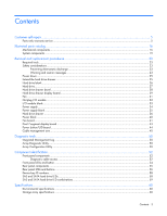
Contents Customer self repair ...5 Parts only warranty service ...5 Illustrated parts catalog ...16 Mechanical components...16 System components ...19 Removal and replacement procedures 23 Required tools ...23 Safety considerations ...23 Preventing electrostatic discharge ...23 Warning and caution - HP 600 | HP StorageWorks 600 Modular Disk System Maintenance and Service Guide - Page 4
Acronyms and abbreviations...61 Index...62 Contents 4 - HP 600 | HP StorageWorks 600 Modular Disk System Maintenance and Service Guide - Page 5
period HP (or HP service providers or service partners) identifies that the repair can be accomplished by the use of a CSR part, HP will ship is required, you can call the HP Technical Support Center and a technician will help you over the telephone. HP specifies in the materials shipped with a - HP 600 | HP StorageWorks 600 Modular Disk System Maintenance and Service Guide - Page 6
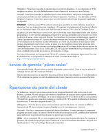
pièce défectueuse, HP se réserve le droit de vous facturer les coûts de remplacement. Dans le cas d'une pièce CSR, HP supporte l'ensemble des frais le site Web HP (http://www.hp.com/go/selfrepair). Service de garantie "pièces seules" Votre garantie limitée HP peut inclure un service de garantie "pi - HP 600 | HP StorageWorks 600 Modular Disk System Maintenance and Service Guide - Page 7
Sie jedoch den Austausch dieser Teile von HP vornehmen lassen möchten, können bei diesem Service je nach den für Ihr Produkt vorgesehenen verfügbar. Wenn Sie Hilfe benötigen, können Sie das HP technische Support Center anrufen und sich von einem Mitarbeiter per Telefon helfen lassen. Den - HP 600 | HP StorageWorks 600 Modular Disk System Maintenance and Service Guide - Page 8
CSR-Verfahren zwingend vorgegeben. Wenn Sie den Austausch dieser Teile von HP vornehmen lassen, werden Ihnen die Anfahrt- und Arbeitskosten für diesen Service berechnet. Reparaciones del propio cliente Los productos de HP incluyen muchos componentes que el propio usuario puede reemplazar (Customer - HP 600 | HP StorageWorks 600 Modular Disk System Maintenance and Service Guide - Page 9
minimum beperkt kan blijven en de flexibiliteit in het vervangen van defecte onderdelen groter is. Deze onderdelen worden CSR-onderdelen (Customer Self Repair) genoemd. Als HP (of een HP Service Partner) bij de diagnose vaststelt dat de reparatie kan worden uitgevoerd met een CSR-onderdeel, verzendt - HP 600 | HP StorageWorks 600 Modular Disk System Maintenance and Service Guide - Page 10
voor meer informatie over het Customer Self Repair programma van HP. Informatie over Service Partners vindt u op de HP website (http://www.hp.com/go/selfrepair). Garantieservice "Parts Only" Het is mogelijk dat de HP garantie alleen de garantieservice "Parts Only" omvat. Volgens de bepalingen - HP 600 | HP StorageWorks 600 Modular Disk System Maintenance and Service Guide - Page 11
No caso desse serviço, a substituição de peças CSR é obrigatória. Se desejar que a HP substitua essas peças, serão cobradas as despesas de transporte e mão-de-obra do serviço. Customer self repair 11 - HP 600 | HP StorageWorks 600 Modular Disk System Maintenance and Service Guide - Page 12
Customer self repair 12 - HP 600 | HP StorageWorks 600 Modular Disk System Maintenance and Service Guide - Page 13
Customer self repair 13 - HP 600 | HP StorageWorks 600 Modular Disk System Maintenance and Service Guide - Page 14
Customer self repair 14 - HP 600 | HP StorageWorks 600 Modular Disk System Maintenance and Service Guide - Page 15
Customer self repair 15 - HP 600 | HP StorageWorks 600 Modular Disk System Maintenance and Service Guide - Page 16
Optional2 Mandatory1 Mandatory1 1Mandatory-Parts for which customer self repair is mandatory. If you request HP to replace these parts, you will be charged for the travel and labor costs of this service. 2Optional-Parts for which customer self repair is optional. These parts are also designed for - HP 600 | HP StorageWorks 600 Modular Disk System Maintenance and Service Guide - Page 17
optional ist. Diese Teile sind auch für Customer Self Repair ausgelegt. Wenn Sie jedoch den Austausch dieser Teile von HP vornehmen lassen möchten, können bei diesem Service je nach den für Ihr Produkt vorgesehenen Garantiebedingungen zusätzliche Kosten anfallen. 3No: Kein-Einige Teile sind nicht - HP 600 | HP StorageWorks 600 Modular Disk System Maintenance and Service Guide - Page 18
Illustrated parts catalog 18 - HP 600 | HP StorageWorks 600 Modular Disk System Maintenance and Service Guide - Page 19
System components Item 6 7 8 9 10 Description Spare part number I/O module with tray and cable Fan Power supply Power block board kit a) UID/power switch board with cables - HP 600 | HP StorageWorks 600 Modular Disk System Maintenance and Service Guide - Page 20
- - * Not shown 1Mandatory-Parts for which customer self repair is mandatory. If you request HP to replace these parts, you will be charged for the travel and labor costs of this service. 2Optional-Parts for which customer self repair is optional. These parts are also designed for customer self - HP 600 | HP StorageWorks 600 Modular Disk System Maintenance and Service Guide - Page 21
optional ist. Diese Teile sind auch für Customer Self Repair ausgelegt. Wenn Sie jedoch den Austausch dieser Teile von HP vornehmen lassen möchten, können bei diesem Service je nach den für Ihr Produkt vorgesehenen Garantiebedingungen zusätzliche Kosten anfallen. 3No: Kein-Einige Teile sind nicht - HP 600 | HP StorageWorks 600 Modular Disk System Maintenance and Service Guide - Page 22
Illustrated parts catalog 22 - HP 600 | HP StorageWorks 600 Modular Disk System Maintenance and Service Guide - Page 23
Before performing service procedures, review all the safety information. Preventing electrostatic discharge To prevent damaging the system, be or damage to equipment, heed all warnings and cautions throughout the installation instructions. WARNING: To reduce the risk of personal injury or damage to - HP 600 | HP StorageWorks 600 Modular Disk System Maintenance and Service Guide - Page 24
, especially when the HP MDS600 Disk System is not fastened to the rack. • Never stack an HP MDS600 Disk System on top of another HP MDS600 Disk System. • Never place equipment on top of an HP MDS600 Disk System. • Never place an HP MDS600 Disk System on a surface that cannot support up to 163 - HP 600 | HP StorageWorks 600 Modular Disk System Maintenance and Service Guide - Page 25
and/or the system. Use caution when performing other operations, such as hot-plug installations or troubleshooting. CAUTION: Protect injury or damage to the equipment, do not extend the hard drive drawers beyond the supporting surface when the unit is not installed in a rack. WARNING: To reduce the - HP 600 | HP StorageWorks 600 Modular Disk System Maintenance and Service Guide - Page 26
3. Extend the hard drive drawer. WARNING: Pinch hazard-Keep hands out of front and rear of chassis when closing hard drive drawers. CAUTION: To prevent improper cooling and thermal damage, do not operate the MDS600 for an extended period of time with the drawer open. Hard drive blank CAUTION: To - HP 600 | HP StorageWorks 600 Modular Disk System Maintenance and Service Guide - Page 27
do the following: • Verify the status of the drive to be replaced by reviewing the SAS and SATA hard drive LEDs (on page 58) and SAS and SATA is removed. For more information, see the HP Array Configuration Utility User Guide on the HP website (http://www.hp.com). • Be sure that the replacement hard - HP 600 | HP StorageWorks 600 Modular Disk System Maintenance and Service Guide - Page 28
2. Remove the hard drive. To replace the component: 1. Fully extend the hard drive lever. 2. Push the hard drive all the way into the drive bay, and then close the lever. Hard drive drawer bezel To remove the component: 1. Power down the MDS600 ("Power down" on page 25). 2. Extend the hard drive - HP 600 | HP StorageWorks 600 Modular Disk System Maintenance and Service Guide - Page 29
4. Remove the eight T-8 Torx screws securing the bezel to the hard drive drawer. 5. Be sure the drawer handle is in the down position. 6. Lean the bezel forward, and then remove it from the hard drive drawer. To replace the component, reverse the removal procedure. The screws are different lengths. - HP 600 | HP StorageWorks 600 Modular Disk System Maintenance and Service Guide - Page 30
For the location of these device bays, see "Device bay ID numbers (on page 58)." 5. Remove the hard drive drawer bezel ("Hard drive drawer bezel" on page 28). 6. Remove the T-15 Torx screw securing the display board assembly to the hard drive drawer, and then lift the assembly straight up to remove - HP 600 | HP StorageWorks 600 Modular Disk System Maintenance and Service Guide - Page 31
a fan. Before removing a fan, do the following: • Verify the status of the fan to be replaced by reviewing rear panel LEDs and buttons (on page 56). • Be sure that your configuration can support your actions. If the proper redundancy is not in place, power down the MDS600 before beginning this - HP 600 | HP StorageWorks 600 Modular Disk System Maintenance and Service Guide - Page 32
the component, be sure to do the following: • Verify the status of the I/O module to be replaced by reviewing rear panel LEDs and buttons (on page 56). • Be sure that your configuration can support your actions. If the proper redundancy is not in place, power down the MDS600 before beginning this - HP 600 | HP StorageWorks 600 Modular Disk System Maintenance and Service Guide - Page 33
3. Release the I/O handle, push the I/O handle down until it ejects the I/O module, and then remove the I/O module. CAUTION: For best cooling practices, do not operate the enclosure for extended periods with more than one component or blank removed. When removing an active component permanently, - HP 600 | HP StorageWorks 600 Modular Disk System Maintenance and Service Guide - Page 34
, be sure to do the following: • Verify the status of the power supply to be replaced by reviewing rear panel LEDs and buttons (on page 56). • Be sure that your configuration can support your actions. If the proper redundancy is not in place, power down the MDS600 before beginning this procedure - HP 600 | HP StorageWorks 600 Modular Disk System Maintenance and Service Guide - Page 35
2. Remove the component as indicated. To replace the component, reverse the removal procedure. Power supply blank CAUTION: For best cooling practices, do not operate the enclosure for extended periods with more than one component or blank removed. When removing an active component permanently, - HP 600 | HP StorageWorks 600 Modular Disk System Maintenance and Service Guide - Page 36
damage to the equipment, do not extend the hard drive drawers beyond the supporting surface when the unit is not installed in a rack. WARNING: To reduce reach inside the chassis while the system is powered up. • Perform service on system components only as instructed in the user documentation. 10. - HP 600 | HP StorageWorks 600 Modular Disk System Maintenance and Service Guide - Page 37
11. Extend the hard drive drawer until it clicks. 12. Compress the cable management arm and push toward the drawer to lock it into place. Removal and replacement procedures 37 - HP 600 | HP StorageWorks 600 Modular Disk System Maintenance and Service Guide - Page 38
of the chassis and align the four rails on the left side and bottom of the drawer bay. CAUTION: To avoid damage to the equipment, HP recommends using two people to perform this step. Removal and replacement procedures 38 - HP 600 | HP StorageWorks 600 Modular Disk System Maintenance and Service Guide - Page 39
3. Push the drawer in about 25 cm (10 in). 4. Release the cable management arm and expand to the rear of the chassis. 5. Push the drawer in another 25 cm (10 in). 6. Install the power block ("Power block" on page 40). WARNING: Pinch hazard-Keep hands out of front and rear of chassis when closing - HP 600 | HP StorageWorks 600 Modular Disk System Maintenance and Service Guide - Page 40
Power block To remove the component: 1. Power down the MDS600 ("Power down" on page 25). 2. Disconnect all cables. 3. Remove all power supplies ("Power supply" on page 34). 4. Remove all fan modules ("Fan" on page 31). 5. Remove all I/O modules ("Hot-plug I/O module" on page 32). 6. Disengage the - HP 600 | HP StorageWorks 600 Modular Disk System Maintenance and Service Guide - Page 41
8. While supporting the power block, disconnect the signal and power cables on each side of the power block. To replace the component, reverse the removal procedure. Fan - HP 600 | HP StorageWorks 600 Modular Disk System Maintenance and Service Guide - Page 42
10. Remove the four T-10 Torx screws securing the fan cage to the hard drive drawer, and then remove the fan cage. 11. Remove the two T-15 Torx screws securing the fan board to the hard drive drawer, and then remove the fan board, being careful not to disconnect the two cables. Removal and - HP 600 | HP StorageWorks 600 Modular Disk System Maintenance and Service Guide - Page 43
12. Disconnect the cables. To replace the component, reverse the removal procedure. Dual 7-segment display board To remove the component: 1. Power down the MDS600 ("Power down" on page 25). 2. Disconnect all cables. 3. Remove all power supplies ("Power supply" on page 34). 4. Remove the fans ("Fan" - HP 600 | HP StorageWorks 600 Modular Disk System Maintenance and Service Guide - Page 44
7. Disconnect the signal cables, remove the four T-15 Torx screws securing the dual 7-segment display board to the power block, and then remove the 7-segment display board. To replace the component, reverse the removal procedure. Power button/UID board To remove the component: 1. Power down the - HP 600 | HP StorageWorks 600 Modular Disk System Maintenance and Service Guide - Page 45
7. Disconnect the signal cables, remove the four T-15 Torx screws securing the power button/UID board to the power block, and then remove the power button/UID board. To replace the component, reverse the removal procedure. Cable management arm To remove the component: 1. Power down the MDS600 (" - HP 600 | HP StorageWorks 600 Modular Disk System Maintenance and Service Guide - Page 46
10. Located behind the cable management arm, remove the T-15 Torx screw that secures the cables to the hard drive drawer, and then remove the cables. 11. Located behind the cable management arm, lift up on the tab to release the latch, and then slide the cable management arm off to remove it. 12. - HP 600 | HP StorageWorks 600 Modular Disk System Maintenance and Service Guide - Page 47
13. Remove the 11 screws securing the backplane cover plate. The screws are different sizes. Use the following illustration and table to identify and keep track of the screws. Item 1 2 3 Description Flushmount T-10 Torx screws T-15 Torx screws 5/8-in T-15 Torx screws 14. Remove the backplane - HP 600 | HP StorageWorks 600 Modular Disk System Maintenance and Service Guide - Page 48
15. Disconnect the cables. When reconnecting the cables, use the following illustration and table to be sure the cables are properly reconnected. Item 1 2 3 4 5 Description Fan signal cable Red 12V power cable Black GND cable Fan power cable Power signal cable 1. Thread the cables through the - HP 600 | HP StorageWorks 600 Modular Disk System Maintenance and Service Guide - Page 49
CAUTION: To avoid damage to the equipment, be sure that the cables are properly connected. The red cable is 12V. The black cable is GND. 2. Install the backplane board: a. Be sure the board is lined up on the standoffs. b. Install the screws. 3. Connect the LED panel cable. 4. Install the cover. 5. - HP 600 | HP StorageWorks 600 Modular Disk System Maintenance and Service Guide - Page 50
CD or downloaded from the HP website (http://www.hp.com). Array Configuration Utility NOTE: ACU does not support mixing SAS and SATA drives in the same logical volume. ACU is a browser-based utility with the following features: • Runs as a local application or remote service • Supports online array - HP 600 | HP StorageWorks 600 Modular Disk System Maintenance and Service Guide - Page 51
systems require Internet Explorer 5.5 (with Service Pack 1) or later. For Linux servers, refer to the README.TXT file for additional browser and support information. For more information, refer to the Configuring Arrays on HP Smart Array Controllers Reference Guide on the Documentation CD or the HP - HP 600 | HP StorageWorks 600 Modular Disk System Maintenance and Service Guide - Page 52
panel components Item 1 2 3 4 Description Drawer 1 Drawer 1 diagnostic cable access (For use by authorized HP personnel only) Drawer 2 Drawer 2 diagnostic cable access (For use by authorized HP personnel only) Diagnostic cable access IMPORTANT: Use of the diagnostic cable connectors is reserved - HP 600 | HP StorageWorks 600 Modular Disk System Maintenance and Service Guide - Page 53
To access the connectors for diagnostic cables, use a small flat-head screwdriver to lift up and release the access tab. Component identification 53 - HP 600 | HP StorageWorks 600 Modular Disk System Maintenance and Service Guide - Page 54
Front panel LEDs and button Item 1 Description Hard drive LEDs Normal mode (UID LED is solid) Status Green = The drive is online, but is not currently active. Flashing irregularly green = The drive is active and it is operating normally. Flashing green (1 Hz) = Do not remove the drive. Removing - HP 600 | HP StorageWorks 600 Modular Disk System Maintenance and Service Guide - Page 55
is enabled from the UID button Blue flashing = Item 1 is in locate mode Off = UID LED is disabled Green = System health is good Off = System is off Amber = Enclosure requires service check: I/O, fan and power supply LEDs, and AC power cables to power supplies. Off = Enclosure is functioning normally - HP 600 | HP StorageWorks 600 Modular Disk System Maintenance and Service Guide - Page 56
1 connector SAS port 2 connector Secondary I/O module (Drawer 2) Fan module 2 (Drawer 2) Power supply 2 Rear panel LEDs and buttons Item 1 Description Status Power On/Standby button and system power LED Green = On Amber = Standby (auxiliary power present) Off = Off Component identification 56 - HP 600 | HP StorageWorks 600 Modular Disk System Maintenance and Service Guide - Page 57
Item 2 3 4 5 6 7 8 9 Description Status Internal Health LED Green = System health is good. Off = System is off. GSI LED Amber = Enclosure requires service check: I/O, fan and power supply LEDs, and AC power cables to power supplies. Off = Enclosure is functioning normally. UID button/LED ( - HP 600 | HP StorageWorks 600 Modular Disk System Maintenance and Service Guide - Page 58
Device bay ID numbers SAS and SATA hard drive LEDs Item 1 2 Description Fault/UID LED (amber/blue) Online LED (green) Component identification 58 - HP 600 | HP StorageWorks 600 Modular Disk System Maintenance and Service Guide - Page 59
SAS and SATA hard drive LED combinations Online/activity Fault/UID LED LED (green) (amber/blue) On, off, or flashing Alternating amber and blue On, off, or flashing Steadily blue On On Flashing regularly (1 Hz) Amber, flashing regularly (1 Hz) Off Amber, flashing regularly (1 Hz) Flashing - HP 600 | HP StorageWorks 600 Modular Disk System Maintenance and Service Guide - Page 60
Specifications Environmental specifications Specification Value Temperature range* Operating Storage 10°C to 35°C (50°F to 95°F) Maximum rate of change is 10º C/hr (50º F/hr) -30°C to 60°C (-22°F to 140°F) Maximum rate of change is 20º C/hr (68º F/hr) Relative humidity** Operating Storage 10% - HP 600 | HP StorageWorks 600 Modular Disk System Maintenance and Service Guide - Page 61
Utility CPLD complex programmable logic device GSI global service indicator I/O input/output IML Integrated Management Log PIC peripheral interface controller SAS serial attached SCSI SATA serial ATA SES SCSI Enclosure Services SIM Systems Insight Manager UID unit identification Acronyms and - HP 600 | HP StorageWorks 600 Modular Disk System Maintenance and Service Guide - Page 62
36 hard drive LEDs 58 hard drives 27 I I/O module 32 I/O module blank 33 IML (Integrated Management Log) 50 L LED, heartbeat 54, 56 LED, system fault 54, 56 LED, system power 56 LED, UID 54 LEDs 52, 56, 58 LEDs, fan 56 LEDs, front panel 54 LEDs, hard drive 58 LEDs, I/O module 56 - HP 600 | HP StorageWorks 600 Modular Disk System Maintenance and Service Guide - Page 63
SAS/SATA LED combinations 59 SATA hard drive LEDs 58, 59 specifications 60 static electricity 23 system components 19, 52 U utilities 50 W warnings 23 Index 63
-
 1
1 -
 2
2 -
 3
3 -
 4
4 -
 5
5 -
 6
6 -
 7
7 -
8
-
9
-
10
-
11
-
12
-
13
-
14
-
15
-
16
-
17
-
18
-
19
-
20
-
21
-
22
-
23
-
24
-
25
-
26
-
27
-
28
-
29
-
30
-
31
-
32
-
33
-
34
-
35
-
36
-
37
-
38
-
39
-
40
-
41
-
42
-
43
-
44
-
45
-
46
-
47
-
48
-
49
-
50
-
51
-
52
-
53
-
54
-
55
-
56
-
57
-
58
-
59
-
60
-
61
-
62
-
63
 |
 |

HP StorageWorks 600 Modular Disk System
Maintenance and Service Guide
Abstract
This guide describes identification and maintenance procedures, diagnostic tools, specifications and requirements for hardware components and
software. This guide is for an experienced service technician. HP assumes you are qualified in the servicing of computer equipment, trained in
recognizing hazards in products, and are familiar with weight and stability precautions.
Part Number: 495106-007
February 2011
Edition: 7