HP 600 HP StorageWorks 600 Modular Disk System Maintenance and Service Guide - Page 30
Remove the T-15 Torx screw securing the display board assembly to the hard drive drawer, and then lift
 |
View all HP 600 manuals
Add to My Manuals
Save this manual to your list of manuals |
Page 30 highlights
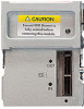
For the location of these device bays, see "Device bay ID numbers (on page 58)." 5. Remove the hard drive drawer bezel ("Hard drive drawer bezel" on page 28). 6. Remove the T-15 Torx screw securing the display board assembly to the hard drive drawer, and then lift the assembly straight up to remove it from the drawer. 7. Turn the display board assembly over, remove the two T-15 Torx screws securing the board to the cover, and lift the board straight out. Removal and replacement procedures 30
-
 1
1 -
2
-
3
-
4
-
5
-
6
-
7
-
8
-
9
-
10
-
11
-
12
-
13
-
14
-
15
-
16
-
17
-
18
-
19
-
20
-
21
-
22
-
23
-
24
-
 25
25 -
 26
26 -
 27
27 -
 28
28 -
 29
29 -
 30
30 -
 31
31 -
 32
32 -
 33
33 -
 34
34 -
 35
35 -
36
-
37
-
38
-
39
-
40
-
41
-
42
-
43
-
44
-
45
-
46
-
47
-
48
-
49
-
50
-
51
-
52
-
53
-
54
-
55
-
56
-
57
-
58
-
59
-
60
-
61
-
62
-
63
 |
 |

Removal and replacement procedures
30
For the location of these device bays, see "Device bay ID numbers (on page
58
)."
5.
Remove the hard drive drawer bezel ("
Hard drive drawer bezel
" on page
28
).
6.
Remove the T-15 Torx screw securing the display board assembly to the hard drive drawer, and then lift
the assembly straight up to remove it from the drawer.
7.
Turn the display board assembly over, remove the two T-15 Torx screws securing the board to the cover,
and lift the board straight out.