HP BL260c HP BladeSystem c-Class Site Planning Guide
HP BL260c - ProLiant - G5 Manual
 |
UPC - 883585668663
View all HP BL260c manuals
Add to My Manuals
Save this manual to your list of manuals |
HP BL260c manual content summary:
- HP BL260c | HP BladeSystem c-Class Site Planning Guide - Page 1
HP BladeSystem c-Class Site Planning Guide Part Number 443250-002 January 2009 (Second Edition) - HP BL260c | HP BladeSystem c-Class Site Planning Guide - Page 2
is for the person who plans for and installs HP BladeSystem c-Class products. Only persons experienced in server blade technology and configuration should attempt these procedures. HP assumes you are qualified in the installation and servicing of computer equipment and trained in recognizing hazards - HP BL260c | HP BladeSystem c-Class Site Planning Guide - Page 3
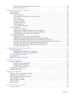
19 Blanking panels...19 HP Rack Airflow Optimization Kit ...19 Space requirements ...19 Delivery space requirements ...20 Operational space requirements...20 Equipment clearance and floor loading 20 Floor plan grid ...21 HP BladeSystem enclosure environmental specifications 22 Rack and accessory - HP BL260c | HP BladeSystem c-Class Site Planning Guide - Page 4
49 Three-phase HP 2400W Power Supply specification (International 50 DC power supply specification ...50 Hardware specifications and requirements 51 Enclosure specifications...51 HP BladeSystem c7000 Enclosure specifications 51 HP BladeSystem c3000 Enclosure specifications 51 HP 10000 G2 rack - HP BL260c | HP BladeSystem c-Class Site Planning Guide - Page 5
Formulas ...66 Technical support...67 Before you contact HP...67 HP contact information ...67 Acronyms and abbreviations...68 Glossary ...70 Index...72 Contents 5 - HP BL260c | HP BladeSystem c-Class Site Planning Guide - Page 6
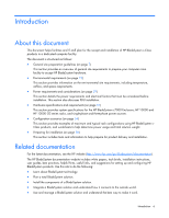
the power requirements and electrical factors that must be considered before installation. This section also discusses PDU installation. • Hardware specifications and requirements (on page 51) This section provides system specifications for the HP BladeSystem c7000 Enclosure, HP 10000 and HP 10000 - HP BL260c | HP BladeSystem c-Class Site Planning Guide - Page 7
data center site and install and configure your systems: • HP Quick Assessment for BladeSystem Environments-The HP BladeSystem Assessment Service is designed to help you determine the capability of your data center environment to meet current and future HP BladeSystem requirements, including the - HP BL260c | HP BladeSystem c-Class Site Planning Guide - Page 8
levels to meet your specific requirements. • HP Datacenter Site Planning Service-Obtain a comprehensive site-preparation audit to help you successfully integrate new equipment into your facility. Service deliverables include verification of installation and service space, examination of the capacity - HP BL260c | HP BladeSystem c-Class Site Planning Guide - Page 9
requirements Air conditioning equipment requirements and recommendations are described in the following sections. Basic air conditioning equipment requirements The cooling capacity of the installed Efficiency Test). Air conditioning system types HP recommends the following air conditioning system - HP BL260c | HP BladeSystem c-Class Site Planning Guide - Page 10
cold condensers An increasing number of in-row cooling supply air is then available near the cooling air intake vents of the racks. Air conditioning system specifications All air conditioning equipment, materials, and installation must comply with any applicable construction codes. Installation - HP BL260c | HP BladeSystem c-Class Site Planning Guide - Page 11
increase. Cabling requirements HP recommends using overhead cabling systems in high-density environments. Placing the cables in overhead raceways maximizes airflow and makes access for servicing and upgrades more efficient. The cable lengths are determined by the cabling specifications for the type - HP BL260c | HP BladeSystem c-Class Site Planning Guide - Page 12
rack weight Cannot ship with equipment installed - For more information, see the following websites: • Best practices for HP 10000 Series and HP 10000 G2 Series Racks on the HP website (http://h20000.www2.hp.com/bc/docs/support/SupportManual/c00883424/c00883424.pdf). • Rack and power page on the HP - HP BL260c | HP BladeSystem c-Class Site Planning Guide - Page 13
for details. • Be aware of power voltages and use trained personnel-Some Enterprise products are capable of producing hazardous voltages and hazardous energy levels. The installation of internal options and routine maintenance and service of these products should be performed only by individuals - HP BL260c | HP BladeSystem c-Class Site Planning Guide - Page 14
lighting, with manual override switches for use during extended occupancy periods or for servicing, is more efficient and less costly. For example, adequate lighting reduces the chance of connector damage when cables are installed or removed. The HP Rack Light Kit (part number 361589B21) can - HP BL260c | HP BladeSystem c-Class Site Planning Guide - Page 15
requirements Environmental elements The following environmental elements can affect HP BladeSystem c-Class product installation develop between connections and lead during service operations speed printer paper feed problems. Low humidity levels are particles can cause power supply and other electronic - HP BL260c | HP BladeSystem c-Class Site Planning Guide - Page 16
are formed on the bottom of some raised floor tiles. Although this problem is relatively rare, it may be an issue within your computer room HP strongly recommends that your site be evaluated for metallic particulate contamination before installation of electronic equipment. Environmental requirements - HP BL260c | HP BladeSystem c-Class Site Planning Guide - Page 17
Maintain recommended humidity level and airflow rates in the computer room. • Install conductive flooring (conductive adhesive must be used when laying tiles). • specification Declared noise emission values for the c7000 enclosure in accordance with ISO 9296: Specification Declared sound power - HP BL260c | HP BladeSystem c-Class Site Planning Guide - Page 18
values in each row meet or exceed the stated industry equivalent class specifications. 4 With installed media, the minimum temperature is 10ºC and maximum relative humidity is limited to 80%. Specific media requirements may vary. 5 Allowable: equipment design extremes as measured at the equipment - HP BL260c | HP BladeSystem c-Class Site Planning Guide - Page 19
rack to meet the airflow requirements of the installed equipment in the rack. Idle, normal operating, and maximum airflow requirements for blade configurations can be obtained from the HP Blade Power Sizer on the HP website (http://www.hp.com/go/bladesystem/powercalculator). Route cables away from - HP BL260c | HP BladeSystem c-Class Site Planning Guide - Page 20
to components. • At least 380 mm (15 in) of clearance is needed around a power supply to facilitate servicing. For more information, see "Working space for component access (on page 14)". Delivery space requirements There should be enough clearance to move equipment safely from the receiving area to - HP BL260c | HP BladeSystem c-Class Site Planning Guide - Page 21
When configuring a solution, make sure that the floor loading specifications are followed. Failure to do so can result in physical conditioning vents • Lighting fixtures • Utility outlets • Doors • Access areas for power wiring and air conditioning filters • Equipment cable routing Environmental - HP BL260c | HP BladeSystem c-Class Site Planning Guide - Page 22
HP BladeSystem enclosure environmental specifications Specification Value Temperature range* Operating 10°C to 35°C (50°F to 95°F) Non-operating Wet . Footprint for a 600 mm rack configuration with an extension kit installed (598 mm wide x 1184.9 mm deep): Environmental requirements 22 - HP BL260c | HP BladeSystem c-Class Site Planning Guide - Page 23
a 600 mm rack configuration with an extension and heavy duty stabilizer kit installed (1001.5 mm wide x 1414.7 mm deep): Front door clearance When door on the left side or remove the door from the rack being serviced. Slight differences exist between the opening allowances of the 10000 and 10000 - HP BL260c | HP BladeSystem c-Class Site Planning Guide - Page 24
• 90º access with one door closed • 120º access with both doors open Front door clearance for 10000 Series Racks configured with 24-in baying brackets is: • 102º access with one door closed Environmental requirements 24 - HP BL260c | HP BladeSystem c-Class Site Planning Guide - Page 25
one door closed • 118º access with both doors open Front door clearance for 10000 G2 Series Racks configured with 24 in baying brackets is: Environmental requirements 25 - HP BL260c | HP BladeSystem c-Class Site Planning Guide - Page 26
connect adjacent racks to create a row of two or more units. Racks that are bayed together with a baying kit are more stable and reduce the potential tipping of the rack. If racks are secured together with baying kits, the side feet installed on each end and support when equipment is installed, - HP BL260c | HP BladeSystem c-Class Site Planning Guide - Page 27
to individual rack installations as well as when aligning rack rows so that the front doors are facing each other. In the rear of the rack, a clearance of 762 mm (30 in) is required to provide space for servicing the rack. If a data center has multiple rows of racks, the rows of racks - HP BL260c | HP BladeSystem c-Class Site Planning Guide - Page 28
accept the adjustable rack rails that are shipped with each enclosure: o Minimum rail length: 635 mm (25 in) o Maximum rail length: 864 mm (9.1 in) 462 mm (18.2 in) For more information, see the HP 10000 G2 Series Rack Tie-Down Option Kit Installation Instructions. Environmental requirements 28 - HP BL260c | HP BladeSystem c-Class Site Planning Guide - Page 29
, do not overload the AC supply branch circuit that provides power to the rack. Consult the electrical authority having jurisdiction over wiring and installation requirements of your facility. CAUTION: Protect the enclosure from power fluctuations and temporary interruptions with a regulating - HP BL260c | HP BladeSystem c-Class Site Planning Guide - Page 30
the c7000 enclosure (5 years) the power supply is rated at 2400W output, 2780VA input. When running in N+N redundant mode, according to the power supply specifications, the system is rated at a maximum input power of 8340VA (2780VA x 3). To deliver this much redundant power to an enclosure requires - HP BL260c | HP BladeSystem c-Class Site Planning Guide - Page 31
. This method would also require ongoing monitoring of the installation to ensure that infrastructure is not overloaded as applications and loads change. • Manage the electrical load using several available HP BladeSystem features. A Dynamic Power Cap can be set at the enclosure level. The Onboard - HP BL260c | HP BladeSystem c-Class Site Planning Guide - Page 32
out loss of service. Use the following guidelines to provide the best possible performance of power distribution systems for HP computer equipment: • Dedicated power source-Isolates the power distribution system from other circuits in the facility. • Online uninterruptible power supply (UPS)-Keeps - HP BL260c | HP BladeSystem c-Class Site Planning Guide - Page 33
, connect each piece of equipment within the rack to a dedicated branch circuit. For additional information, see the HP website http://www.hp.com/og/powercapping. Power options The following table describes the available power options and provide details about those options. Enclosure part number - HP BL260c | HP BladeSystem c-Class Site Planning Guide - Page 34
N+N design: N power supplies can be provided where N/2 power supplies are capable of sustaining the associated equipment's power demand. For the c7000 enclosure, this quantity is typically a 2+2 or 3+3 power supply configuration. • N+1 design: Typically four power supplies are provided, requiring at - HP BL260c | HP BladeSystem c-Class Site Planning Guide - Page 35
. Furthermore, be sure that all power distribution devices used in the installation, such as branch wiring and receptacles, are Listed or Certified grounding-type devices. Observe the following limits when connecting products to AC power distribution devices: Power requirements and considerations 35 - HP BL260c | HP BladeSystem c-Class Site Planning Guide - Page 36
. Power distribution systems consist of several parts. HP recommends that these parts be solidly interconnected to provide an equipotential ground to all points. Main building electrical ground The main electrical service entrance equipment should have an earth ground connection, as required by - HP BL260c | HP BladeSystem c-Class Site Planning Guide - Page 37
service. Cabinet performance grounding (high frequency ground) Some safety power power distribution system 50-60Hz grounding system. HP recommends the use of a properly installed pedestals. • Connect the opposite corners two corners at opposite ends of the row is Power requirements and considerations 37 - HP BL260c | HP BladeSystem c-Class Site Planning Guide - Page 38
compound (similar to Burndy Penetrox). System installation guidelines In domestic installations, install the proper receptacles before the HP equipment arrives. For installation procedures, see the appropriate installation guide. Wiring connections Expansion and contraction rates vary among - HP BL260c | HP BladeSystem c-Class Site Planning Guide - Page 39
the HP website (http://www.hp.com/go/bladesystem). Dynamic Power Capping The Dynamic Power Capping feature limits the power consumption of the enclosure through enclosure Dynamic Power Cap settings within the Onboard Administrator. The enclosure Dynamic Power Cap is shared among all of the installed - HP BL260c | HP BladeSystem c-Class Site Planning Guide - Page 40
• HP BladeSystem c3000 Enclosure • HP BladeSystem c3000 Tower Enclosure Power requirements and considerations 40 - HP BL260c | HP BladeSystem c-Class Site Planning Guide - Page 41
• HP BladeSystem c7000 Enclosure To cable the enclosure using a single-phase AC configuration: 1. Connect the AC power cables to the power connectors on the rear of the enclosure corresponding to the power supply that was populated on the front of the enclosure. 2. Connect the AC power cables to the - HP BL260c | HP BladeSystem c-Class Site Planning Guide - Page 42
Administrator. The time it takes to complete initialization depends on the number of server blades configured in the enclosure. For example, a full enclosure of 16 server blades might take 5 minutes to power up, while an enclosure with fewer server blades might take less time. When first initialized - HP BL260c | HP BladeSystem c-Class Site Planning Guide - Page 43
of three c7000 enclosures connected to HP S348 (part number AF916A) PDUs. This specific wiring configuration is used to ensure that the load is evenly balanced across all three phases of the incoming circuit, even with Dynamic Power Saver enabled. Enclosure/switch Power supply Switch C Switch - HP BL260c | HP BladeSystem c-Class Site Planning Guide - Page 44
Enclosure/switch Power supply Switch A Enclosure C Enclosure C Enclosure C Enclosure C Enclosure C Enclosure C Enclosure B Enclosure B Enclosure B Enclosure B Enclosure B Enclosure B Enclosure A Enclosure A Enclosure A Enclosure A Enclosure A Enclosure A Single PS6 PS5 PS4 PS3 PS2 PS1 PS6 PS5 PS4 - HP BL260c | HP BladeSystem c-Class Site Planning Guide - Page 45
configuration with 24A single-phase PDU HP BladeSystem c7000 Enclosure three-phase AC configuration To cable the enclosure using a three-phase AC configuration: 1. The AC power cables are already attached to the enclosure. 2. Connect the AC power cables to the AC power source. 3. Turn on the AC - HP BL260c | HP BladeSystem c-Class Site Planning Guide - Page 46
HP website (http://www.hp.com/go/bladesystem). HP BladeSystem c7000 Enclosure DC configuration Item 1 2 3 4 5 6 7 8 9 10 Description Chassis grounding lugs DC connectors for power supply bay 1 DC connectors for power supply bay 2 DC connectors for power supply bay 3 DC connectors for power supply - HP BL260c | HP BladeSystem c-Class Site Planning Guide - Page 47
HP BladeSystem c3000 Enclosure DC configuation HP BladeSystem c3000 Enclosure HP BladeSystem c3000 Tower Enclosure Power supply specifications Single-phase HP 2250W Power Supply specification Specification Power cord Output Input requirements Value IEC-320 C19-C20 1.22 m (4 ft) 2250 W per power - HP BL260c | HP BladeSystem c-Class Site Planning Guide - Page 48
200 VAC to 240 VAC Single-phase HP 2400W High Efficiency Power Supply specification Specification Power cord Output Input requirements Rated input voltage Rated input frequency Rated input current per power supply (maximum) Rated input power per power supply (maximum) Value IEC-320 C19-C20 1.22 - HP BL260c | HP BladeSystem c-Class Site Planning Guide - Page 49
208 VAC Input requirements Rated input voltage 200 VAC to 220 VAC line-to-line 3-phase Delta Rated input frequency 50 Hz to 60 Hz Rated input power per power 8340VA cord (maximum) Three-phase HP 2250W Power Supply specification (International) Specification Value Power cords (2) IEC-309 - HP BL260c | HP BladeSystem c-Class Site Planning Guide - Page 50
HP 2400W Power Supply specification (International) Specification Value Power cords (2) IEC-309 200/346-V to 240/415-V, 5-pin, 16-A 2.44 m (10 ft) Max input current per line cord 12.6 A at 220 VAC 11.5 A at 240 VAC Max input power per line cord 8340 VA Maximum Input requirements Rated - HP BL260c | HP BladeSystem c-Class Site Planning Guide - Page 51
HP BladeSystem c7000 Enclosure specifications Specification Product dimensions Height Depth Width Shipping dimensions Height Depth Width Single-phase enclosure weight* Unboxed Shipping Three-phase enclosure weight* Unboxed Shipping Maximum enclosure weight Unboxed Shipping * No components installed - HP BL260c | HP BladeSystem c-Class Site Planning Guide - Page 52
Standard enclosure weight * Unboxed 65.80 kg (145.00 lb) Shipping Maximum enclosure weight Unboxed Shipping 88.50 kg (195.00 lb) 136.00 kg (300.00 lb) 158.80 kg (350.00 lb) * Includes two power supplies, four fans, and one Onboard Administrator. HP 10000 G2 rack specifications For a current - HP BL260c | HP BladeSystem c-Class Site Planning Guide - Page 53
requirements The HP BladeSystem c7000 Enclosure (referred to as the enclosure) can be used in a rack-free environment. The following conditions must be met when performing a rack-free installation: • A fully-populated enclosure can weigh up to 217.7 kg (480 lb). The object supporting the enclosure - HP BL260c | HP BladeSystem c-Class Site Planning Guide - Page 54
0 mA 70 A Total system weight (includes power and rack) 197 kg (435 lb) Power credentials Total input power Total input VA BTU Total input power summary is based on the following configuration: • HP BladeSystem c7000 enclosure (1) • HP Virtual Connect Ethernet Modules (2) • HP Virtual Connect - HP BL260c | HP BladeSystem c-Class Site Planning Guide - Page 55
maximum configuration This power summary is based on the following configuration: • HP BladeSystem c7000 Enclosure (1) • HP Virtual Connect Ethernet Modules (2) • HP Virtual Connect Fibre Channel Modules (2) • HP 4X DDR InfiniBand Switch Module for HP c-Class BladeSystem (1) • HP ProLiant BL460 - HP BL260c | HP BladeSystem c-Class Site Planning Guide - Page 56
rack and determine its power consumption. See the HP website (http://www.hp.com/go/bladesystem/powercalculator). For other models, obtain the power consumption data from a component's specifications. The QuickSpecs contains the specifications for all HP products. Photocopy the following worksheet - HP BL260c | HP BladeSystem c-Class Site Planning Guide - Page 57
. To obtain the weight of any individual component, see the QuickSpecs on the HP website. Component Quantity Weight (kg) Weight (lb) Total Rack Enclosure weight including all components Other rack options and requirements Option A Option B Option C Total weight Configuration scenarios 57 - HP BL260c | HP BladeSystem c-Class Site Planning Guide - Page 58
injury or damage to the equipment: • Observe local occupational health and safety requirements and guidelines for manual material handling. • Remove all installed enclosure components from their enclosures before installing or moving the enclosures. • Use caution and get help to lift and stabilize - HP BL260c | HP BladeSystem c-Class Site Planning Guide - Page 59
a power failure. IMPORTANT: Data on the dimensions and weights of HP BladeSystem c-Class components can be found in the HP BladeSystem c-Class Maintenance and Service Guide. The same data can be determined by using the online HP BladeSystem c-Class Sizing Utility. Preparing for installation 59 - HP BL260c | HP BladeSystem c-Class Site Planning Guide - Page 60
Additional rack considerations Consider the following additional specifications and components, with regard to your specific rack configuration: • Power-If a UPS is installed, do not exceed its output rating. Be sure to review the installation instructions provided with each component for important - HP BL260c | HP BladeSystem c-Class Site Planning Guide - Page 61
factory default racking. The latest version of this software is available on the HP website (http://h30099.www3.hp.com/eGlue/eco/begin.do). When loading your components, observe the general guidelines: • For detailed instructions on installing specific component or third-party hardware, see the user - HP BL260c | HP BladeSystem c-Class Site Planning Guide - Page 62
coordination meeting arranged with an HP representative to review the inspection checklist and arrange an installation schedule • 7 days before installation o Final check made with an HP site preparation specialist to resolve any last minute problems Sample checklists Customer and Hewlett - HP BL260c | HP BladeSystem c-Class Site Planning Guide - Page 63
and lighting 13. Are lighting levels adequate for maintenance? 14. Are AC outlets available for servicing needs? (for example, vacuuming) 15. Does the input voltage correspond to equipment specifications? 16. Is a dual power source used? If so, identify type and evaluate grounding. 17. Does the - HP BL260c | HP BladeSystem c-Class Site Planning Guide - Page 64
or recommendations form. The following list gives examples of special instructions or issues: • Packaging restrictions at the facility, such as size and weight limitations • Special delivery procedures • Special equipment required for installation, such as tracking or hoists • What time the facility - HP BL260c | HP BladeSystem c-Class Site Planning Guide - Page 65
Elevator Capacity (kg or lb): Depth: Height: Width: Stairs Number of flights: Width: Preparing for installation 65 - HP BL260c | HP BladeSystem c-Class Site Planning Guide - Page 66
factors The conversion factors provided here are intended to help in data calculation for systems that do not conform to the specific configurations listed in this guide. Listed below are the conversion factors used in this document, as well as additional conversion factors that can be helpful in - HP BL260c | HP BladeSystem c-Class Site Planning Guide - Page 67
to have the following information available before you call HP: • Technical support registration number (if applicable) • Product serial number • Product model name and number • Product identification number • Applicable error messages • Add-on boards or hardware • Third-party hardware or software - HP BL260c | HP BladeSystem c-Class Site Planning Guide - Page 68
return air EMI electromagnetic interference EMT electrical metallic tubing ESD electrostatic discharge LAHJ local authority has jurisdiction PDU power distribution unit RFI radio frequency interference RMS root-mean-square SRG signal reference grid TMRA recommended ambient operating temperature - HP BL260c | HP BladeSystem c-Class Site Planning Guide - Page 69
UPS uninterruptible power system Acronyms and abbreviations 69 - HP BL260c | HP BladeSystem c-Class Site Planning Guide - Page 70
product of RMS current times RMS voltage, without taking the power weight by the area of its footprint. This value is expressed in kg/m2 (lb/ft2). BTU/h The abbreviation for British thermal units per hour. The amount of heat required load The load that a floor panel can support on a 6.45 cm2 (1 in2) - HP BL260c | HP BladeSystem c-Class Site Planning Guide - Page 71
from step 2 is found. rolling load The load a floor panel can support (without failure) when a wheel of specified diameter and width is rolled across A unit of electricity consumption representing the product of amperage and voltage. When the power requirement of a product is listed in watts, - HP BL260c | HP BladeSystem c-Class Site Planning Guide - Page 72
supply 46, 50 delivery survey 64 distribution hardware 34 dust and pollution control 15 Dynamic Power Cap 39 E earth leakage current 35 electrical conduits 35 electrical factors 29 electrical load requirements 31 electrical requirements 29, 31 electrostatic discharge 17 enclosure specifications - HP BL260c | HP BladeSystem c-Class Site Planning Guide - Page 73
, delivery 20 space requirements, operational 20 specifications 47, 50, 51 support 67 T technical support 67 telephone numbers 67 third-party racks 27 three-phase AC configuration 45 W warnings 20, 37, 53, 58 website, HP 67 weight, estimating 57 wire selection 34 wiring connections 38 Index 73
-
 1
1 -
 2
2 -
 3
3 -
 4
4 -
 5
5 -
 6
6 -
 7
7 -
8
-
9
-
10
-
11
-
12
-
13
-
14
-
15
-
16
-
17
-
18
-
19
-
20
-
21
-
22
-
23
-
24
-
25
-
26
-
27
-
28
-
29
-
30
-
31
-
32
-
33
-
34
-
35
-
36
-
37
-
38
-
39
-
40
-
41
-
42
-
43
-
44
-
45
-
46
-
47
-
48
-
49
-
50
-
51
-
52
-
53
-
54
-
55
-
56
-
57
-
58
-
59
-
60
-
61
-
62
-
63
-
64
-
65
-
66
-
67
-
68
-
69
-
70
-
71
-
72
-
73
 |
 |

HP BladeSystem c-Class
Site Planning Guide
Part Number 443250-002
January 2009 (Second Edition)