HP BL260c HP BladeSystem c-Class Site Planning Guide - Page 38
Equipment grounding implementation details, System installation guidelines, Wiring connections
 |
UPC - 883585668663
View all HP BL260c manuals
Add to My Manuals
Save this manual to your list of manuals |
Page 38 highlights
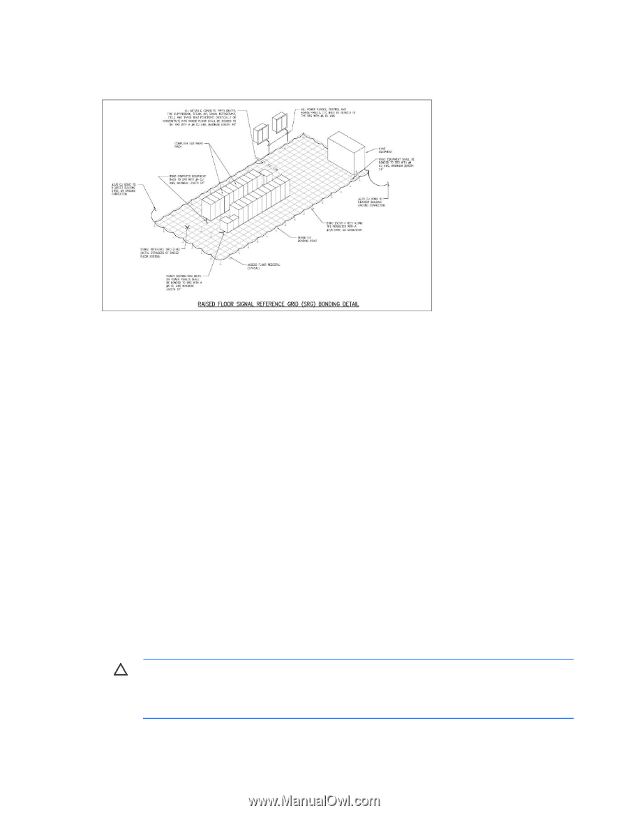
• Add a grounding grid made of copper strips mounted to the subfloor. The strips should be 0.8 mm (0.032 in) thick and a minimum of 76 mm (3.0 in) wide. Connect each pedestal to four strips using 6-mm (0.25-in) bolts tightened to the manufacturer's torque recommendation. Equipment grounding implementation details Connect all HP equipment cabinets to the site ground grid as follows: 1. Attach one end of each ground strap to the applicable cabinet ground lug. 2. Attach the other end to the nearest pedestal base (raised floor) or cable trough ground point (nonraised floor). 3. Check that the braid contact on each end of the ground strap consists of a terminal and connection hardware (a 6-mm [0.25-in] bolt, nuts, and washers). 4. Check that the braid contact connection points are free of paint or other insulating material and treated with a contact enhancement compound (similar to Burndy Penetrox). System installation guidelines In domestic installations, install the proper receptacles before the HP equipment arrives. For installation procedures, see the appropriate installation guide. Wiring connections Expansion and contraction rates vary among different metals. Therefore, the integrity of an electrical connection depends on the restraining force applied. Connections that are too tight can compress or deform the hardware and cause it to weaken. This deformation usually leads to high impedance, preventing circuit breakers from tripping when needed or contributing to a buildup of high frequency noise. CAUTION: Connections that are too loose or too tight can have a high impedance that causes serious problems, such as erratic equipment operation. A high impedance connection overheats and sometimes causes fire or high temperatures that can destroy hard-to-replace components such as distribution panels or system bus bars. Power requirements and considerations 38
-
 1
1 -
2
-
3
-
4
-
5
-
6
-
7
-
8
-
9
-
10
-
11
-
12
-
13
-
14
-
15
-
16
-
17
-
18
-
19
-
20
-
21
-
22
-
23
-
24
-
25
-
26
-
27
-
28
-
29
-
30
-
31
-
32
-
 33
33 -
 34
34 -
 35
35 -
 36
36 -
 37
37 -
 38
38 -
 39
39 -
 40
40 -
 41
41 -
 42
42 -
 43
43 -
44
-
45
-
46
-
47
-
48
-
49
-
50
-
51
-
52
-
53
-
54
-
55
-
56
-
57
-
58
-
59
-
60
-
61
-
62
-
63
-
64
-
65
-
66
-
67
-
68
-
69
-
70
-
71
-
72
-
73
 |
 |