HP Nc6400 HP Compaq nc6400 Notebook PC Maintenance and Service Guide
HP Nc6400 - Compaq Business Notebook Manual
 |
View all HP Nc6400 manuals
Add to My Manuals
Save this manual to your list of manuals |
HP Nc6400 manual content summary:
- HP Nc6400 | HP Compaq nc6400 Notebook PC Maintenance and Service Guide - Page 1
HP Compaq nc6400 Notebook PC Document Part Number: 406847-003 March 2007 This guide is a troubleshooting reference used for maintaining and servicing the computer. It provides comprehensive information on identifying computer features, components, and spare parts; troubleshooting computer problems - HP Nc6400 | HP Compaq nc6400 Notebook PC Maintenance and Service Guide - Page 2
herein should be construed as constituting an additional warranty. HP shall not be liable for technical or editorial errors or omissions contained herein. Maintenance and Service Guide HP Compaq nc6400 Notebook PC Third Edition: March 2007 First Edition: May 2006 Document Part Number: 406847-003 - HP Nc6400 | HP Compaq nc6400 Notebook PC Maintenance and Service Guide - Page 3
surface, such as an adjoining optional printer, or a soft surface, such as pillows or rugs or clothing, to block airflow. Also, do not allow the AC adapter to contact the skin or a soft surface, such as pillows or rugs or clothing, during operation. The computer and the - HP Nc6400 | HP Compaq nc6400 Notebook PC Maintenance and Service Guide - Page 4
1.2 Resetting the Computer 1-4 1.3 Power Management 1-5 1.4 External Components 1-6 1.5 Design Overview 1-24 2 Troubleshooting 2.1 2-3 File Menu 2-4 Security Menu 2-5 Diagnostics Menu 2-7 System Configuration Menu 2-7 2.2 Troubleshooting Flowcharts 2-10 Maintenance and Service Guide iv - HP Nc6400 | HP Compaq nc6400 Notebook PC Maintenance and Service Guide - Page 5
Display Assembly Components 3-16 3.4 Plastics Kit 3-18 3.5 Cable Kit 3-19 3.6 Mass Storage Devices 3-20 3.7 Miscellaneous (Not Illustrated 3-21 3.8 Sequential Part Number Listing 3-23 4 Removal and Replacement Preliminaries 4.1 Tools Required 4-1 4.2 Service Considerations 4-2 Plastic Parts - HP Nc6400 | HP Compaq nc6400 Notebook PC Maintenance and Service Guide - Page 6
RTC Battery 5-28 5.12 Internal Memory Module 5-29 5.13 Modem Module 5-31 5.14 Mini Card WWAN Module 5-33 5.15 Switch Cover 5-35 5.16 Power Button Board 5-37 5.17 Fan Assembly 5-38 5.18 Heat Sink 5-39 5.19 Processor 5-42 5.20 Display Assembly 5-44 5.21 Top Cover 5-55 5.22 PC Card/Digital - HP Nc6400 | HP Compaq nc6400 Notebook PC Maintenance and Service Guide - Page 7
Contents 6 Specifications A Screw Listing B Backup and Recovery in Windows Vista C Backup and Recovery in Windows XP D Display Component Recycling E Connector Pin Assignments F Power Cord Set Requirements Index vii Maintenance and Service Guide - HP Nc6400 | HP Compaq nc6400 Notebook PC Maintenance and Service Guide - Page 8
1 Product Description The HP Compaq nc6400 Notebook PC offers advanced modularity, Intel® Core™ Duo, Core Solo, and Celeron® processors, and extensive multimedia support. HP Compaq nc6400 Notebook PC Maintenance and Service Guide 1-1 - HP Nc6400 | HP Compaq nc6400 Notebook PC Maintenance and Service Guide - Page 9
GB ■ Microsoft® Windows Vista™ Business, Windows Vista Home Basic, and Windows® XP Professional ■ Full-size Windows keyboard with numeric keypad ■ TouchPad and pointing stick pointing devices, including a dedicated vertical scroll region ■ Integrated 10 Base-T/100 Base-TX Ethernet local area network - HP Nc6400 | HP Compaq nc6400 Notebook PC Maintenance and Service Guide - Page 10
LAN (WLAN) device ■ Support for one Type I or Type II PC Card slot, with support for both 32-bit (CardBus) and 16-bit PC Cards, varying by computer model ■ External 90- and 65-watt AC adapters with 3-wire power cord, varying by computer model ■ 8-cell and 4-cell Li-Ion batteries ■ Stereo speakers - HP Nc6400 | HP Compaq nc6400 Notebook PC Maintenance and Service Guide - Page 11
RTC battery). 3. Wait approximately 5 minutes. 4. Replace the RTC battery and reassemble the computer. 5. Connect AC power to the computer. Do not reinsert any batteries at this time. 6. Turn on the computer. All passwords and all CMOS settings have been cleared. 1-4 Maintenance and Service Guide - HP Nc6400 | HP Compaq nc6400 Notebook PC Maintenance and Service Guide - Page 12
power management features: ■ Standby ■ Hibernation ■ Setting customization by the user ■ Hotkeys for setting the level of performance ■ Battery calibration ■ Lid switch standby/resume ■ Power button ■ Advanced Configuration and Power Management (ACPM) compliance Maintenance and Service Guide - HP Nc6400 | HP Compaq nc6400 Notebook PC Maintenance and Service Guide - Page 13
(LAN) device and/or a Bluetooth® device, is turned on. ■ On: The computer is on. ■ Blinking: The computer is in standby. ■ Blinking rapidly: An HP Smart AC Adapter with a higher power rating should be connected. ■ Off: The computer is off or in hibernation. 1-6 Maintenance and Service Guide - HP Nc6400 | HP Compaq nc6400 Notebook PC Maintenance and Service Guide - Page 14
wireless communication between the computer and an optional IrDA-compliant device. Digital Media Slot Supports Secure Digital (SD) Memory Cards and MultiMediaCards (MMC). Stereo speakers (2) Produce stereo sound. Display release latch Opens the computer. Maintenance and Service Guide 1-7 - HP Nc6400 | HP Compaq nc6400 Notebook PC Maintenance and Service Guide - Page 15
Product Description The external components on the right side of the computer are shown below and described in Table 1-2. Right-Side Components 1-8 Maintenance and Service Guide - HP Nc6400 | HP Compaq nc6400 Notebook PC Maintenance and Service Guide - Page 16
Supports an optical disc. The type of optical drive varies by computer model. USB port Connects USB 1.1- and 2.0-compliant devices to the computer using a standard USB cable, or connects an optional External MultiBay II to the computer. The MultiBay II must also be connected to an external power - HP Nc6400 | HP Compaq nc6400 Notebook PC Maintenance and Service Guide - Page 17
Product Description The external components on the left side of the computer are shown below and described in Table 1-3. Left-Side Components 1-10 Maintenance and Service Guide - HP Nc6400 | HP Compaq nc6400 Notebook PC Maintenance and Service Guide - Page 18
microphone. Audio-out (headphone) jack Produces computer sound when connected to optional power stereo speakers, headphones, ear buds, a headset, or television audio. PC Card slot Supports optional Type I or Type II 32-bit (CardBus) or 16-bit PC Cards. Maintenance and Service Guide 1-11 - HP Nc6400 | HP Compaq nc6400 Notebook PC Maintenance and Service Guide - Page 19
Product Description The external components on the rear panel of the computer are shown below and described in Table 1-4. Rear Panel Components 1-12 Maintenance and Service Guide - HP Nc6400 | HP Compaq nc6400 Notebook PC Maintenance and Service Guide - Page 20
Connects an AC adapter or an optional power adapter. S-Video-out jack Connects an optional S-Video device, such as a television, VCR, camcorder, projector, or video capture card. External monitor port Connects an optional VGA external monitor or projector. Maintenance and Service Guide 1-13 - HP Nc6400 | HP Compaq nc6400 Notebook PC Maintenance and Service Guide - Page 21
Product Description The standard keyboard components of the computer are shown below and described in Table 1-5. Standard Keyboard Components 1-14 Maintenance and Service Guide - HP Nc6400 | HP Compaq nc6400 Notebook PC Maintenance and Service Guide - Page 22
be used like the keys on an external numeric keypad. Arrow keys Moves the cursor around the screen. Windows applications key In Windows, displays a shortcut menu for items beneath the pointer. Windows logo key In Windows, displays the Windows Start menu. Maintenance and Service Guide 1-15 - HP Nc6400 | HP Compaq nc6400 Notebook PC Maintenance and Service Guide - Page 23
Product Description The computer top components are shown below and described in Table 1-6. Top Components 1-16 Maintenance and Service Guide - HP Nc6400 | HP Compaq nc6400 Notebook PC Maintenance and Service Guide - Page 24
Power button When the computer is: ■ Off, press to turn on the computer. ■ On, briefly press to initiate hibernation. ■ In standby, briefly press to resume from standby. ■ In hibernation, briefly press to restore from hibernation. If the system has stopped responding and Windows Service Guide 1-17 - HP Nc6400 | HP Compaq nc6400 Notebook PC Maintenance and Service Guide - Page 25
Product Description The computer top components are shown below and described in Table 1-7. Top Components 1-18 Maintenance and Service Guide - HP Nc6400 | HP Compaq nc6400 Notebook PC Maintenance and Service Guide - Page 26
local area network (LAN) device and/or a Bluetooth® device, is turned on. Caps lock light On: caps lock is on. Num lock light On: num lock or the numeric keypad is on. Fingerprint reader Allows a fingerprint logon to Windows instead of using a password. Maintenance and Service Guide 1-19 - HP Nc6400 | HP Compaq nc6400 Notebook PC Maintenance and Service Guide - Page 27
Product Description The computer pointing device components are shown below and described in Table 1-8. Pointing Device Components 1-20 Maintenance and Service Guide - HP Nc6400 | HP Compaq nc6400 Notebook PC Maintenance and Service Guide - Page 28
Product Description Item 1 2 3 4 5 Table 1-8 Pointing Device Components Component Function Pointing stick Moves the pointer and selects or activates items on the screen. , and right buttons on an external mouse. TouchPad scroll zone Scrolls up or down. Maintenance and Service Guide 1-21 - HP Nc6400 | HP Compaq nc6400 Notebook PC Maintenance and Service Guide - Page 29
Connects the computer to an optional (full-featured models only) docking device. Battery release latches (2) Release the battery from the battery bay. Accessory battery connector Connects an optional HP Ultra-Capacity Battery or HP Extended Life Battery. 1-22 Maintenance and Service Guide - HP Nc6400 | HP Compaq nc6400 Notebook PC Maintenance and Service Guide - Page 30
to cool internal components. Hard drive bay Holds the primary hard drive. Memory module compartment Contains one memory slot that supports replaceable memory modules. Bluetooth compartment Contains a Bluetooth device (select computer models only). Serial number Identifies the computer. This - HP Nc6400 | HP Compaq nc6400 Notebook PC Maintenance and Service Guide - Page 31
parts, and Chapter 5, "Removal and Replacement Procedures," for disassembly steps. The system board provides the following device connections: ■ Audio ■ Display ■ Hard drive ■ Intel Core Duo, Core Solo, and Celeron processors ■ Keyboard and TouchPad ■ Memory modules ■ Mini Card module ■ PC - HP Nc6400 | HP Compaq nc6400 Notebook PC Maintenance and Service Guide - Page 32
may not be supported by your computer. ✎ Pointing devices are not supported in Computer Setup. You must use the keyboard to navigate and make selections. ✎ An external keyboard connected by USB can be used with Computer Setup only if USB legacy support is enabled. Maintenance and Service Guide 2-1 - HP Nc6400 | HP Compaq nc6400 Notebook PC Maintenance and Service Guide - Page 33
Troubleshooting To start Computer Setup: 1. Turn on or restart the computer. 2. Before Windows® opens and while the "F10=ROM Based Setup" message is displayed is displayed in the lower-left corner of the screen. Because Computer Setup is not Windows-based, it does not support the and Service Guide - HP Nc6400 | HP Compaq nc6400 Notebook PC Maintenance and Service Guide - Page 34
F10 = ROM Based Setup" message is displayed in the lower-left corner of the instructions on the screen. Your preferences go into effect when the computer restarts. ✎ Your password settings and security settings are not changed when you restore the factory settings. Maintenance and Service Guide - HP Nc6400 | HP Compaq nc6400 Notebook PC Maintenance and Service Guide - Page 35
supported by your computer. File Menu Table 2-1 File Menu Select To do this System Information ■ View identification information for the computer and the batteries in the system. ■ View specification information for the processor, cache and memory restarts. 2-4 Maintenance and Service Guide - HP Nc6400 | HP Compaq nc6400 Notebook PC Maintenance and Service Guide - Page 36
the computer. Enable/disable support for smart card and Java™ Card power-on authentication. ✎ Power-on authentication for smart cards is supported only on computers with optional smart card readers. ✎ You must have an administrator password to change this setting. Maintenance and Service Guide 2-5 - HP Nc6400 | HP Compaq nc6400 Notebook PC Maintenance and Service Guide - Page 37
Troubleshooting Select TPM Embedded Security System IDs Disk Sanitizer Table 2-2 Security Menu (Continued) To do this Enable/disable support for TPM (Trusted Platform Module) Embedded Security , the data on the primary hard drive is destroyed permanently. 2-6 Maintenance and Service Guide - HP Nc6400 | HP Compaq nc6400 Notebook PC Maintenance and Service Guide - Page 38
boot. ■ Enable/disable internal network adapter boot and set the boot mode (PXE or RPL). ■ Enable/disable MultiBoot, which sets a boot order that can include most boot devices in the system. ■ Set the Express Boot Popup delay in seconds. ■ Set the boot order. Maintenance and Service Guide 2-7 - HP Nc6400 | HP Compaq nc6400 Notebook PC Maintenance and Service Guide - Page 39
, which helps to improve computer security. ■ Enable/disable LAN Power Save. When enabled, saves power by turning off the LAN when not in use. ■ Enable/disable SATA Native Mode. ■ Enable/disable Dual Core CPU. ■ Enable/disable Secondary Battery Fast Charge. 2-8 Maintenance and Service Guide - HP Nc6400 | HP Compaq nc6400 Notebook PC Maintenance and Service Guide - Page 40
LBA assisted HDD Translation Mode. ■ Enable/disable Windows direct application launcher. ■ Enable/disable HP Lockout. ■ Enable/disable embedded WWAN Device Radio. ■ Enable/disable embedded WLAN Device Radio ■ Enable/disable embedded Bluetooth® Device Radio. ■ Enable/disable LAN/WLAN Switching. When - HP Nc6400 | HP Compaq nc6400 Notebook PC Maintenance and Service Guide - Page 41
15-No Audio, Part 1" 2.16 "Flowchart 2.16-No Audio, Part 2" 2.17 "Flowchart 2.17-Nonfunctioning Device" 2.18 "Flowchart 2.18-Nonfunctioning Keyboard" 2.19 "Flowchart 2.19-Nonfunctioning Pointing Device" 2.20 "Flowchart 2.20-No Network/Modem Connection" 2-10 Maintenance and Service Guide - HP Nc6400 | HP Compaq nc6400 Notebook PC Maintenance and Service Guide - Page 42
Initial Troubleshooting Begin troubleshooting. N Is there power? Y Go to "Flowchart 2.2-No Power, Part 1." N Beeps, LEDs, or error messages? Y N Is there video? (no boot) Y N Is the OS loading? Y N Is there sound? Y Check LED board, speaker connections. Y Go to "Flowchart 2.6-No Video, Part - HP Nc6400 | HP Compaq nc6400 Notebook PC Maintenance and Service Guide - Page 43
Flowchart 2.2-No Power, Part 1 No power (power LED is off). Remove from docking device (if applicable). N Power up on battery power? Y Reset power.* N Power up on battery power? Y Go to "Flowchart 2.3-No Power, Part 2." N Power up on AC power? Y Reset power.* N Power up on AC power? Y Go to - HP Nc6400 | HP Compaq nc6400 Notebook PC Maintenance and Service Guide - Page 44
in battery socket and clean if necessary. Y Power on? Done N Check battery by recharging it, moving it to another computer, or replacing it. N Power on? Y Replace power supply (if applicable). N Done Power on? Y Go to "Flowchart 2.4-No Power, Part 3." Done Maintenance and Service Guide - HP Nc6400 | HP Compaq nc6400 Notebook PC Maintenance and Service Guide - Page 45
. Y Power on? N N Power outlet active? Y Replace power cord. Y Power on? N Done Done Try different outlet. External Internal or external AC adapter? Replace external AC adapter. Internal N Go to "Flowchart Power on? 2.5-No Power, Part 4." Y Done Done 2-14 Maintenance and Service Guide - HP Nc6400 | HP Compaq nc6400 Notebook PC Maintenance and Service Guide - Page 46
the following items (if applicable). Check computer operation after each replacement: 1. Internal DC-DC converter* 2. Internal AC adapter 3. Processor board* 4. System board* *NOTE: Replace these items as a set to prevent shorting out among components. Done Maintenance and Service Guide 2-15 - HP Nc6400 | HP Compaq nc6400 Notebook PC Maintenance and Service Guide - Page 47
Troubleshooting Flowchart 2.6-No Video, Part 1 No video. Docking Device Stand-alone or docking device? Go to "Flowchart 2.7-No Video, Part 2." *NOTE: To change from internal to external display, use the hotkey combination. Stand-alone Y Internal or external Adjust brightness. Video OK? - HP Nc6400 | HP Compaq nc6400 Notebook PC Maintenance and Service Guide - Page 48
Troubleshooting Flowchart 2.7-No Video, Part 2 Continued from "Flowchart 2.6-No Video, Part 1." Remove computer from docking device, if connected. Adjust display brightness. Check brightness of external monitor. N Y Go to "A" in Video OK? "Flowchart Video OK? Done 2.6-No Video, Part 1." - HP Nc6400 | HP Compaq nc6400 Notebook PC Maintenance and Service Guide - Page 49
Troubleshooting Flowchart 2.8-Nonfunctioning Docking Device (if applicable) Nonfunctioning docking device. Reset power cord in docking device and power outlet. Check voltage setting on docking device. Reset monitor cable connector at docking device. Y Docking device operating? N Replace docking - HP Nc6400 | HP Compaq nc6400 Notebook PC Maintenance and Service Guide - Page 50
Troubleshooting Flowchart 2.9-No Operating System (OS) Loading No OS loading.* Reset power cord in docking device and power outlet. No OS loading from hard drive, go to "Flowchart 2.10-No OS Loading, Hard Drive, Part 1." No OS loading from diskette drive, go to "Flowchart 2.13-No OS Loading, - HP Nc6400 | HP Compaq nc6400 Notebook PC Maintenance and Service Guide - Page 51
2.11-No OS Loading, Hard Drive, Part 2." Done N Boot from diskette? Y Change boot priority through the Setup Utility and reboot. N Boot from hard drive? Y Go to "Flowchart 2.13-No OS Loading, Diskette Drive." Go to "Flowchart 2.17-Nonfunctioning Device." 2-20 Maintenance and Service Guide - HP Nc6400 | HP Compaq nc6400 Notebook PC Maintenance and Service Guide - Page 52
Troubleshooting Flowchart 2.11-No OS Loading, Hard Drive, Part 2 Continued from "Flowchart 2.10-No OS Loading, Hard Drive, Part "Flowchart 2.12-No OS Loading, Hard Drive, Part 3." N Hard drive partitioned? Y N Hard 2.12-No OS Loading, Hard Drive, Part 3." Create partition, and then format hard - HP Nc6400 | HP Compaq nc6400 Notebook PC Maintenance and Service Guide - Page 53
Troubleshooting Flowchart 2.12-No OS Loading, Hard Drive, Part 3 Continued from "Flowchart 2.11-No OS Loading, Hard Drive, Part 2." N System files on hard drive? Y Install OS and reboot. Y Virus on hard drive? N Run SCANDISK and check for bad sectors. N Can bad sectors be fixed? Y Clean virus. - HP Nc6400 | HP Compaq nc6400 Notebook PC Maintenance and Service Guide - Page 54
1. Replace diskette drive. 2. Replace system board. N Y Reset the computer. Refer to OS loading? Done Section 1.2, "Resetting the N Computer," for instructions. Change boot priority using the Setup Utility. Go to "Flowchart 2.17-Nonfunctioning Device." Maintenance and Service Guide 2-23 - HP Nc6400 | HP Compaq nc6400 Notebook PC Maintenance and Service Guide - Page 55
Troubleshooting Flowchart 2.14-No OS Loading, Device." Y Reset the computer. Booting order correct? N Refer to Section 1.2, "Resetting the Computer," for instructions. Go to "Flowchart 2.17-Nonfunctioning Device." Correct boot order using the Setup Utility. 2-24 Maintenance and Service Guide - HP Nc6400 | HP Compaq nc6400 Notebook PC Maintenance and Service Guide - Page 56
. N Y Computer in docking device (if applicable)? N Undock N Internal audio? Y Go to "Flowchart 2.16-No Audio, Part 2." Go to "Flowchart 2.16-No Audio, Part 2." Replace the docking device. Go to "Flowchart 2.17-Nonfunctioning Device." N Y Audio? Done Maintenance and Service Guide 2-25 - HP Nc6400 | HP Compaq nc6400 Notebook PC Maintenance and Service Guide - Page 57
Troubleshooting Flowchart 2.16-No Audio, Part 2 Continued from "Flowchart 2.15-No Audio, Part 1." N Audio driver in OS configured? Y Reload audio drivers. N Correct drivers for application? Y Load drivers and set configuration in OS. Connect to external speaker. N Replace audio Y board - HP Nc6400 | HP Compaq nc6400 Notebook PC Maintenance and Service Guide - Page 58
? Y Y Any physical device detected? N Replace hard drive. Replace NIC. If integrated NIC, replace system board. Fix or replace broken item. Go to "Flowchart 2.9-No Operating System (OS) Loading." N Device boots properly? Y Done Replace diskette drive. Done Maintenance and Service Guide 2-27 - HP Nc6400 | HP Compaq nc6400 Notebook PC Maintenance and Service Guide - Page 59
operating properly. Connect computer to good external keyboard. N External device works? Y Replace system board. Reseat internal keyboard connector (if applicable). N OK? Y Replace internal keyboard or cable. Y Done OK? Done N Replace system board. 2-28 Maintenance and Service Guide - HP Nc6400 | HP Compaq nc6400 Notebook PC Maintenance and Service Guide - Page 60
. Connect computer to good external pointing device. N External device works? Y Replace system board. Reseat internal pointing device connector (if applicable). N OK? Y Replace internal pointing device or cable. Y Done OK? Done N Replace system board. Maintenance and Service Guide 2-29 - HP Nc6400 | HP Compaq nc6400 Notebook PC Maintenance and Service Guide - Page 61
? Y Replace jack or have jack activated. Y Digital line? N Connect to nondigital line. N Y NIC/modem configured Reload drivers and OK? Done in OS? reconfigure. Y N Disconnect all power from the computer and open. Reseat NIC/modem (if applicable). Replace the NIC/modem (if applicable - HP Nc6400 | HP Compaq nc6400 Notebook PC Maintenance and Service Guide - Page 62
parts breakdown and a reference for spare part numbers. 3.1 Serial Number Location When ordering parts or requesting information, provide the computer serial number and computer model number located on the bottom of the computer. Serial Number Location Maintenance and Service Guide 3-1 - HP Nc6400 | HP Compaq nc6400 Notebook PC Maintenance and Service Guide - Page 63
Illustrated Parts Catalog 3.2 Computer Major Components Computer Major Components 3-2 Maintenance and Service Guide - HP Nc6400 | HP Compaq nc6400 Notebook PC Maintenance and Service Guide - Page 64
14.1-inch, WXGA+ 14.1-inch, WXGA 418907-001 418896-001 Refer to Section 3.3, "Display Assembly Components," for display assembly internal component spare part number information. Switch cover 418900-001 Power button board (includes power 418910-031 418910-001 Maintenance and Service Guide 3-3 - HP Nc6400 | HP Compaq nc6400 Notebook PC Maintenance and Service Guide - Page 65
Illustrated Parts Catalog Computer Major Components 3-4 Maintenance and Service Guide - HP Nc6400 | HP Compaq nc6400 Notebook PC Maintenance and Service Guide - Page 66
Audio cable Bluetooth cable RTC battery Microphone Top cover Top cover (includes TouchPad, smart card reader, and fingerprint reader board) Top cover (includes TouchPad and smart card reader) Plastics Kit PC Card slot bezel Hard drive cover Memory cover Mini Card cover Bluetooth cover PC - HP Nc6400 | HP Compaq nc6400 Notebook PC Maintenance and Service Guide - Page 67
Illustrated Parts Catalog Computer Major Components 3-6 Maintenance and Service Guide - HP Nc6400 | HP Compaq nc6400 Notebook PC Maintenance and Service Guide - Page 68
Computer Major Components (Continued) Item 13 14 15 16 Description Spare Part Number Mini Card WWAN module 418860-001 For use with Verizon networks For use with Vodafone networks For use with Cingular networks 418860-001 435098-001 436668-001 Fan assembly 418886-001 System boards (include - HP Nc6400 | HP Compaq nc6400 Notebook PC Maintenance and Service Guide - Page 69
Illustrated Parts Catalog Computer Major Components 3-8 Maintenance and Service Guide - HP Nc6400 | HP Compaq nc6400 Notebook PC Maintenance and Service Guide - Page 70
Part Number Processors (include thermal grease, alcohol pad, and thermal pad) Intel Core Duo T7600 (2.33-GHz) processor Intel Core Duo T7400 (2.16-GHz) processor Intel Core Duo T7200 (2.0-GHz) processor Intel Core Duo T5600 (1.83-GHz) processor Intel Core Duo 001 Maintenance and Service Guide 3-9 - HP Nc6400 | HP Compaq nc6400 Notebook PC Maintenance and Service Guide - Page 71
Illustrated Parts Catalog Computer Major Components 3-10 Maintenance and Service Guide - HP Nc6400 | HP Compaq nc6400 Notebook PC Maintenance and Service Guide - Page 72
Parts: Computer Major Components (Continued) Item 23 24 25 Description MultiBay II drives (include bezel) DVD±RW and CD-RW Double-Layer Combo Drive DVD±RW and CD-RW Combo Drive DVD-ROM drive Battery /g LJ WLAN module for use in Japan Spare Part Number 418866-001 418865-001 418864-001 418867-001 - HP Nc6400 | HP Compaq nc6400 Notebook PC Maintenance and Service Guide - Page 73
Illustrated Parts Catalog Computer Major Components 3-12 Maintenance and Service Guide - HP Nc6400 | HP Compaq nc6400 Notebook PC Maintenance and Service Guide - Page 74
Catalog Table 3-1 Spare Parts: Computer Major Components (Continued) Item 25 Description Mini Card WLAN modules and Montenegro Singapore Slovakia Liechtenstein Lithuania Luxembourg Malta Monaco The Netherlands Spare Part Number 407576-001 Paraguay Saudi Arabia Taiwan The United States Vietnam - HP Nc6400 | HP Compaq nc6400 Notebook PC Maintenance and Service Guide - Page 75
Illustrated Parts Catalog Computer Major Components 3-14 Maintenance and Service Guide - HP Nc6400 | HP Compaq nc6400 Notebook PC Maintenance and Service Guide - Page 76
module for use in the following countries or regions: Israel Jordan Kuwait Thailand United Arab Emirates Bluetooth® module (includes Bluetooth module cable) Spare Part Number 407576-003 Uruguay Venezuela 407576-291 407576-AD1 409250-004 Ukraine 409993-001 Maintenance and Service Guide 3-15 - HP Nc6400 | HP Compaq nc6400 Notebook PC Maintenance and Service Guide - Page 77
Illustrated Parts Catalog 3.3 Display Assembly Components 3-16 Maintenance and Service Guide - HP Nc6400 | HP Compaq nc6400 Notebook PC Maintenance and Service Guide - Page 78
, WXGA display panel) Display Screw Kit Display Rubber Kit (includes all display bezel rubber and mylar screw covers) Spare Part Number 418889-001 418891-001 418890-001 418902-001 418888-001 418899-001 418895-001 418894-001 418898-001 418897-001 418892-001 418893-001 Maintenance and Service Guide - HP Nc6400 | HP Compaq nc6400 Notebook PC Maintenance and Service Guide - Page 79
C clips) Memory module compartment cover (includes 1 captive screw, captured by C clip) Mini Card module compartment cover (includes 1 captive screw, captured by C clip) Bluetooth module cover (includes 1 captive screw, captured by C clip) Computer feet (4) 3-18 Maintenance and Service Guide - HP Nc6400 | HP Compaq nc6400 Notebook PC Maintenance and Service Guide - Page 80
3.5 Cable Kit Illustrated Parts Catalog Table 3-4 Cable Kit Spare Part Number Information Item 1 2 3 4 5 Description Cable Kit Includes: Pointing stick cable Bluetooth module cable Audio cable Modem module cable TouchPad cable Spare Part Number 418876-001 Maintenance and Service Guide 3-19 - HP Nc6400 | HP Compaq nc6400 Notebook PC Maintenance and Service Guide - Page 81
Catalog 3.6 Mass Storage Devices Item 1 2 Table 3-5 Mass Storage Devices Spare Part Number Information Description Hard drives (include frame DVD±RW and CD-RW Combo Drive DVD-ROM drive Spare Part Number 440880-001 418863-001 418862-001 418859-001 418858-001 418866-001 418865-001 418864- - HP Nc6400 | HP Compaq nc6400 Notebook PC Maintenance and Service Guide - Page 82
Spare Part Information Description 90-watt non-PFC AC adapter 90-watt PFC AC adapter 65-watt PFC AC adapter External MultiBay II Fingerprint reader insert (for use as a filler in a non-used fingerprint reader) External MultiBay II power cable and stand HP Extended Life Battery HP Docking Station HP - HP Nc6400 | HP Compaq nc6400 Notebook PC Maintenance and Service Guide - Page 83
Illustrated) Spare Part Information (Continued) Description Spare Part Number Power cords: For refer to Appendix A, "Screw Listing," for more information on specifications and usage) 418878-001 ■ Phillips PM3.0×3.0 screw ■ Phillips ■ Torx8 T8M2.5×4.0 screw 3-22 Maintenance and Service Guide - HP Nc6400 | HP Compaq nc6400 Notebook PC Maintenance and Service Guide - Page 84
use in Israel Power cord for use in Switzerland Power cord for use in French Canada USB 1.1 diskette drive External MultiBay II External MultiBay II power cable and stand HP Extended Life Battery HP Docking Station HP Docking Station Miscellaneous Plastics Kit Maintenance and Service Guide 3-23 - HP Nc6400 | HP Compaq nc6400 Notebook PC Maintenance and Service Guide - Page 85
Catalog Table 3-7 Sequential Part Number Listing (Continued) Spare Part Number 407107-001 407107-002 407107-291 407108-001 407108-002 407108-291 407576-001 Description Malaysia Mexico New Zealand Paraguay Saudi Arabia Taiwan The United States Vietnam 3-24 Maintenance and Service Guide - HP Nc6400 | HP Compaq nc6400 Notebook PC Maintenance and Service Guide - Page 86
Catalog Table 3-7 Sequential Part Number Listing (Continued) Spare Part Number 407576-002 407576-003 Kuwait Thailand United Arab Emirates Ukraine Bluetooth module (includes Bluetooth module cable) Modem module 1-DIMM, PC2-4200, 256-MB memory module Maintenance and Service Guide 3-25 - HP Nc6400 | HP Compaq nc6400 Notebook PC Maintenance and Service Guide - Page 87
Combo Drive 8-cell, 5.1-AH battery Intel Core Duo T2300 (1.67-GHz) processor (includes thermal paste) Intel Core Duo T2400 (1.83-GHz) processor (includes thermal paste) Intel Core Duo T2500 (2.00-GHz) processor (includes thermal paste) 4-cell, 2.5-AH battery 3-26 Maintenance and Service Guide - HP Nc6400 | HP Compaq nc6400 Notebook PC Maintenance and Service Guide - Page 88
-PFC AC adapter Intel Core Duo T2600 (2.17-GHz) processor (includes thermal paste) 90-watt PFC AC adapter Cable Kit Plastics Kit Screw Kit Label Kit RTC battery Base enclosure Top cover with 3 pointing stick buttons and 3 TouchPad buttons, for use with keyboards with Pointing Stick Speaker PC Card - HP Nc6400 | HP Compaq nc6400 Notebook PC Maintenance and Service Guide - Page 89
use only with heat sink with spare part number 418887-001 (includes thermal grease, alcohol pad, and thermal pad) MultiBay II eject assembly 14.1-inch, WXGA+ display assembly (includes wireless antenna transceivers and cables) Power button board (includes power button board cable) Keyboard for use - HP Nc6400 | HP Compaq nc6400 Notebook PC Maintenance and Service Guide - Page 90
Catalog Table 3-7 Sequential Part Number Listing (Continued) Spare Part Number 418910-041 418910-051 418910-061 418910-071 418910-081 418910-091 418910-101 418910-111 Russia Keyboard for use in Thailand Keyboard for use in Japan Keyboard for use in Belgium Maintenance and Service Guide 3-29 - HP Nc6400 | HP Compaq nc6400 Notebook PC Maintenance and Service Guide - Page 91
Duo T7200 (2.0-GHz) processor Intel Core Duo T5600 (1.83-GHz) processor Intel Core Duo T5500 (1.66-GHz) processor Intel Core Duo T2300E (1.66-GHz) processor Mini Card WWAN module for use with Cingular networks Top cover (includes TouchPad and smart card reader) 3-30 Maintenance and Service Guide - HP Nc6400 | HP Compaq nc6400 Notebook PC Maintenance and Service Guide - Page 92
438170-001 438875-001 438876-001 440880-001 444966-001 444965-001 Description Fingerprint reader insert (for use as a filler in a non-used fingerprint reader) Heat sink for use only with discrete system boards (spare part numbers 418904-001 and 430495-001), includes thermal grease, alcohol pad, and - HP Nc6400 | HP Compaq nc6400 Notebook PC Maintenance and Service Guide - Page 93
4 Removal and Replacement Preliminaries This chapter provides essential information for proper and safe removal and replacement service. 4.1 Tools Required You will need the following tools to complete the removal and replacement procedures: ■ Magnetic screwdriver ■ Phillips P0 and P1 screwdrivers ■ - HP Nc6400 | HP Compaq nc6400 Notebook PC Maintenance and Service Guide - Page 94
Service Considerations parts. Use care when handling the plastic parts. Apply pressure only at the points designated in the maintenance instructions. Cables and Connectors Ä CAUTION: When servicing be caught or snagged by parts being removed or replaced. Handle flex cables with extreme care; - HP Nc6400 | HP Compaq nc6400 Notebook PC Maintenance and Service Guide - Page 95
mailed, place the drive in a bubble pack mailer or other suitable form of protective packaging and label the package "FRAGILE: Handle With Care." Maintenance and Service Guide 4-3 - HP Nc6400 | HP Compaq nc6400 Notebook PC Maintenance and Service Guide - Page 96
power to alter device device exposed to electrostatic discharge might not be affected at all and can work perfectly throughout a normal cycle. Or the device might function normally for a while, then degrade in the internal layers, reducing its life expectancy. 4-4 Maintenance and Service Guide - HP Nc6400 | HP Compaq nc6400 Notebook PC Maintenance and Service Guide - Page 97
containers. ■ Always be properly grounded when touching a sensitive component or assembly. ■ Store reusable electrostatic-sensitive parts from assemblies to avoid static charging. When grounding is not possible, use an ionizer to dissipate electric charges. Maintenance and Service Guide 4-5 - HP Nc6400 | HP Compaq nc6400 Notebook PC Maintenance and Service Guide - Page 98
components, parts, and assemblies by the case or PCM laminate. Handle these items only at static-free workstations. ■ Avoid contact with pins, leads, or circuitry. ■ Turn off power and input signals before inserting or removing connectors or test equipment. 4-6 Maintenance and Service Guide - HP Nc6400 | HP Compaq nc6400 Notebook PC Maintenance and Service Guide - Page 99
with ground cords of one megohm resistance. ■ Static-dissipative tables or floor mats with hard ties to the ground. ■ Field service kits. ■ Static awareness labels. ■ Material-handling packages. ■ Nonconductive plastic bags, tubes, or boxes. ■ Metal tote boxes. ■ Electrostatic voltage levels and - HP Nc6400 | HP Compaq nc6400 Notebook PC Maintenance and Service Guide - Page 100
2,000 V 700 V 400 V Removing DIPS from vinyl tray 11,500 V 4,000 V 2,000 V Removing DIPS from Styrofoam 14,500 V 5,000 V 3,500 V Removing bubble pack from PCB 26,500 V 20,000 V 7,000 V Packing PCBs in mats 7,500 V Metallized laminate Floor mats 5,000 V 4-8 Maintenance and Service Guide - HP Nc6400 | HP Compaq nc6400 Notebook PC Maintenance and Service Guide - Page 101
Replacement Procedures This chapter provides removal and replacement procedures. There are as many as 81 screws, in 14 different sizes, that must be removed, replaced, or loosened when servicing the computer. Make special note of each screw size and location during removal and replacement. Refer to - HP Nc6400 | HP Compaq nc6400 Notebook PC Maintenance and Service Guide - Page 102
Removal and Replacement Procedures 5.1 Serial Number Report the computer serial number to HP when requesting information or ordering spare parts. The serial number is located on the bottom of the computer. Serial Number Location 5-2 Maintenance and Service Guide - HP Nc6400 | HP Compaq nc6400 Notebook PC Maintenance and Service Guide - Page 103
wireless devices in your country or region. If you install a device and then receive a warning message, remove the device to restore computer functionality. Then contact technical support by selecting Start > Help and Support > Contact support.. MultiBay II Device 1 Maintenance and Service Guide - HP Nc6400 | HP Compaq nc6400 Notebook PC Maintenance and Service Guide - Page 104
5.26 Description Keyboard RTC Battery Internal Memory Module Modem Module Mini Card WWAN Module Switch Cover Power Button Board Fan Assembly Heat Sink Processor Display Assembly Display bezel Display hinges Display panel Display inverter Wireless antenna transceivers Top Cover PC Card/Digital Media - HP Nc6400 | HP Compaq nc6400 Notebook PC Maintenance and Service Guide - Page 105
unsure whether the computer is off or in hibernation, turn the computer on, and then shut it down through the operating system. 2. Disconnect all external devices connected to the computer. 3. Disconnect the power cord. Maintenance and Service Guide 5-5 - HP Nc6400 | HP Compaq nc6400 Notebook PC Maintenance and Service Guide - Page 106
toward you. b. Slide the battery release latch on the right 1 and then the battery release latch on the left 2 to release the battery. c. Slide the battery 3 straight back and remove it. Removing the Battery Reverse the above procedure to install the battery. 5-6 Maintenance and Service Guide - HP Nc6400 | HP Compaq nc6400 Notebook PC Maintenance and Service Guide - Page 107
5.4 Hard Drive Removal and Replacement Procedures Hard Drive Spare Part Number Information 7200 rpm 100 GB 80 GB 60 GB 431125-001 431124-001 418861-001 the computer for disassembly (refer to Section 5.3). 2. Position the computer with the front toward you. Maintenance and Service Guide 5-7 - HP Nc6400 | HP Compaq nc6400 Notebook PC Maintenance and Service Guide - Page 108
cover 2 and swing it up and to the left. 5. Remove the hard drive cover. ✎ The hard drive cover is included in the Plastics Kit, spare part number 418877-001. Removing the Hard Drive Cover 5-8 Maintenance and Service Guide - HP Nc6400 | HP Compaq nc6400 Notebook PC Maintenance and Service Guide - Page 109
3 to the left to disconnect it from the system board. 8. Remove the hard drive 4 from the hard drive bay. Removing the Hard Drive Maintenance and Service Guide 5-9 - HP Nc6400 | HP Compaq nc6400 Notebook PC Maintenance and Service Guide - Page 110
remove if from the hard drive. Removing the Hard Drive Frame Reverse the above procedure to reassemble and install the hard drive. 5-10 Maintenance and Service Guide - HP Nc6400 | HP Compaq nc6400 Notebook PC Maintenance and Service Guide - Page 111
Removal and Replacement Procedures 5.5 Computer Feet The computer feet are adhesive-backed rubber pads. The feet are included in the Plastics Kit, spare part number 418877-001. Replacing the Computer Feet Maintenance and Service Guide 5-11 - HP Nc6400 | HP Compaq nc6400 Notebook PC Maintenance and Service Guide - Page 112
cable) 409993-001 1. Prepare the computer for disassembly (refer to Section 5.3). 2. Loosen the Phillips PM2.0×5.0 screw 1 that secures the Bluetooth module cover to the computer. 3. Remove the Bluetooth module cover 2. Removing the Bluetooth Module Cover 5-12 Maintenance and Service Guide - HP Nc6400 | HP Compaq nc6400 Notebook PC Maintenance and Service Guide - Page 113
the Bluetooth module. ✎ The Bluetooth module cable is included with the Bluetooth module spare part kit and is also available in the Cable Kit, spare part number 418876-001. Removing the Bluetooth Module Reverse the above procedure to install a Bluetooth module. Maintenance and Service Guide 5-13 - HP Nc6400 | HP Compaq nc6400 Notebook PC Maintenance and Service Guide - Page 114
Removal and Replacement Procedures 5.7 External Memory Module Memory Module Spare Part Number Information PC2-5300 2048 MB 1024 MB 512 MB 256 MB 418857-001 the computer for disassembly (refer to Section 5.3). 2. Position the computer with the front toward you. 5-14 Maintenance and Service Guide - HP Nc6400 | HP Compaq nc6400 Notebook PC Maintenance and Service Guide - Page 115
Lift the right edge of the cover 2 and swing it up and to the left. 5. Remove the memory module compartment cover. ✎ The memory module compartment cover is included in the Plastics Kit, spare part number 418877-001. Removing the Memory Module Compartment Cover Maintenance and Service Guide 5-15 - HP Nc6400 | HP Compaq nc6400 Notebook PC Maintenance and Service Guide - Page 116
2 away from the socket at an angle. 8. Remove the memory module. ✎ Memory modules are designed with a notch 3 to prevent incorrect installation into the memory module socket. Removing the Memory Module Reverse the above procedure to install a memory module. 5-16 Maintenance and Service Guide - HP Nc6400 | HP Compaq nc6400 Notebook PC Maintenance and Service Guide - Page 117
Removal and Replacement Procedures 5.8 Mini Card WLAN Module Mini Card WLAN Module Spare Part Number Information 802.11b/g HS WLAN module for use in North America 407107-001 Malaysia Mexico New Zealand Paraguay Saudi Arabia Taiwan The United States Vietnam Maintenance and Service Guide 5-17 - HP Nc6400 | HP Compaq nc6400 Notebook PC Maintenance and Service Guide - Page 118
Removal and Replacement Procedures Mini Card WLAN Module Spare Part Number Information (Continued) 802.11a/b/g GL WLAN module for use in the countries or 407576-002 countries 409250-004 or regions: Israel Jordan Kuwait Thailand United Arab Emirates Ukraine 5-18 Maintenance and Service Guide - HP Nc6400 | HP Compaq nc6400 Notebook PC Maintenance and Service Guide - Page 119
the back of the computer. 5. Remove the Mini Card module compartment cover. ✎ The Mini Card module compartment cover is included in the Plastics Kit, spare part number 418877-001. Removing the Mini Card Module Compartment Cover Maintenance and Service Guide 5-19 - HP Nc6400 | HP Compaq nc6400 Notebook PC Maintenance and Service Guide - Page 120
the Mini Card WLAN module. ✎ The wireless antenna cables are available in the Wireless Antenna Kit, spare part number 418899-001. 7. Remove the two Phillips PM2.0×3.0 screws 2 that secure the Mini Card WLAN the above procedure to install a Mini Card WLAN module. 5-20 Maintenance and Service Guide - HP Nc6400 | HP Compaq nc6400 Notebook PC Maintenance and Service Guide - Page 121
Device Spare Part Number Information DVD±RW and CD-RW Double-Layer Combo Drive DVD±RW and CD-RW Combo Drive DVD-ROM drive 418866-001 418865-001 418864-001 1. Prepare the computer for disassembly (Section 5.3). 2. Position the computer with the left side toward you. Maintenance and Service Guide - HP Nc6400 | HP Compaq nc6400 Notebook PC Maintenance and Service Guide - Page 122
on the right side of the MultiBay II device 2. (The MultiBay II device partially protrudes from the MultiBay II.) 5. Slide the MultiBay II device 3 out of the computer. Removing the MultiBay II Device Reverse the above procedure to install an MultiBay II device. 5-22 Maintenance and Service Guide - HP Nc6400 | HP Compaq nc6400 Notebook PC Maintenance and Service Guide - Page 123
5.10 Keyboard Removal and Replacement Procedures Keyboard Spare Part Number Information For use in: Belgium Brazil The Czech Republic Denmark France French Canada the computer for disassembly (Section 5.3). 2. Position the computer with the front toward you. Maintenance and Service Guide 5-23 - HP Nc6400 | HP Compaq nc6400 Notebook PC Maintenance and Service Guide - Page 124
Removal and Replacement Procedures 3. Remove the three Torx8 T8M2.5×11.0 screws that secure the keyboard to the computer. Removing the Keyboard Screws 5-24 Maintenance and Service Guide - HP Nc6400 | HP Compaq nc6400 Notebook PC Maintenance and Service Guide - Page 125
Removal and Replacement Procedures 4. Turn the computer display-side up with the front toward you. 5. Open the computer as far as possible. 6. Slide the four release keyboard 2 and swing it up toward you until it rests on the palm rest. Releasing the Keyboard Maintenance and Service Guide 5-25 - HP Nc6400 | HP Compaq nc6400 Notebook PC Maintenance and Service Guide - Page 126
pointing stick cable is attached and disconnect the pointing stick cable 4. 10. Remove the keyboard. Disconnecting the Keyboard and Pointing Stick Cables 5-26 Maintenance and Service Guide - HP Nc6400 | HP Compaq nc6400 Notebook PC Maintenance and Service Guide - Page 127
attached and disconnect the pointing stick cable 2. ✎ The pointing stick cable is included with all keyboard spare part kits and is also available in the Cable Kit, spare part number 418876-001. Removing the Pointing Stick Cable Reverse the above procedure to install the keyboard. Maintenance and - HP Nc6400 | HP Compaq nc6400 Notebook PC Maintenance and Service Guide - Page 128
remove the cable from the clips 2 in the top cover. 4. Remove the RTC battery 3 from the clip in the base enclosure. ✎ The RTC battery is secured to the top cover by two-sided tape. Removing the RTC Battery Reverse the above procedure to install an RTC battery. 5-28 Maintenance and Service Guide - HP Nc6400 | HP Compaq nc6400 Notebook PC Maintenance and Service Guide - Page 129
Removal and Replacement Procedures 5.12 Internal Memory Module Memory Module Spare Part Number Information PC2-5300 2048 MB 1024 MB 512 MB 256 MB 418857-001 -001 1. Prepare the computer for disassembly (Section 5.3). 2. Release the keyboard (Section 5.10). Maintenance and Service Guide 5-29 - HP Nc6400 | HP Compaq nc6400 Notebook PC Maintenance and Service Guide - Page 130
2 away from the socket at an angle. 5. Remove the memory module. ✎ Memory modules are designed with a notch 3 to prevent incorrect installation into the memory module socket. Removing the Memory Module Reverse the above procedure to install a memory module. 5-30 Maintenance and Service Guide - HP Nc6400 | HP Compaq nc6400 Notebook PC Maintenance and Service Guide - Page 131
Removal and Replacement Procedures 5.13 Modem Module Modem Module Spare Part Number Information Modem module 418849-001 1. Prepare the computer for disassembly (Section 5.3). 2. Release the keyboard (Section 5.10). Maintenance and Service Guide 5-31 - HP Nc6400 | HP Compaq nc6400 Notebook PC Maintenance and Service Guide - Page 132
the modem module cable 3 from the modem module. ✎ The modem module cable is included in the modem module spare part kit and is also available in the Cable Kit, spare part number 418876-001. 6. Remove the modem module. Removing the Modem Module Reverse the above procedure to install the modem - HP Nc6400 | HP Compaq nc6400 Notebook PC Maintenance and Service Guide - Page 133
WWAN Module Spare Part Number Information For use with Verizon networks For use with Vodafone networks For use with Cingular networks 418860-001 435098-001 436668-001 1. Prepare the computer for disassembly (Section 5.3). 2. Release the keyboard (Section 5.10). Maintenance and Service Guide 5-33 - HP Nc6400 | HP Compaq nc6400 Notebook PC Maintenance and Service Guide - Page 134
the Mini Card WWAN module. ✎ The wireless antenna cables are available in the Wireless Antenna Kit, spare part number 418899-001. 4. Remove the two Phillips PM2.0×3.0 screws 2 that secure the Mini Card WWAN the above procedure to install a Mini Card WWAN module. 5-34 Maintenance and Service Guide - HP Nc6400 | HP Compaq nc6400 Notebook PC Maintenance and Service Guide - Page 135
Removal and Replacement Procedures 5.15 Switch Cover Switch Cover Spare Part Number Information Switch cover 418900-001 1. Prepare the computer for disassembly (Section 5.3). 2. Remove secure the switch cover to the computer. Removing the Switch Cover Screws Maintenance and Service Guide 5-35 - HP Nc6400 | HP Compaq nc6400 Notebook PC Maintenance and Service Guide - Page 136
Removal and Replacement Procedures 5. Turn the computer display-side up with front toward you. 6. Open the computer as far as possible. 7. Disconnect the power button board cable 1 from the system board. 8. Insert the above procedure to install the switch cover. 5-36 Maintenance and Service Guide - HP Nc6400 | HP Compaq nc6400 Notebook PC Maintenance and Service Guide - Page 137
5.15). 4. Remove the two Phillips PM2.5×4.0 screws 1 that secure the power button board to the switch cover. 5. Remove the power button board 2 from the switch cover. Removing the Power Button Board Reverse the above procedure to install the power button board. Maintenance and Service Guide 5-37 - HP Nc6400 | HP Compaq nc6400 Notebook PC Maintenance and Service Guide - Page 138
the fan cable 1 from the system board. 5. Remove the Torx8 T8M2.5×7.0 screw 2 that secures the fan assembly to the base enclosure. 6. Remove the fan assembly 3 from the computer. Removing the Fan Assembly Reverse the above procedure to install the fan assembly. 5-38 Maintenance and Service Guide - HP Nc6400 | HP Compaq nc6400 Notebook PC Maintenance and Service Guide - Page 139
with discrete system boards For use only with the UMA system board (spare part number 418931-001) For use only with the UMA system board 418887-001 Keyboard (Section 5.10) b. Switch cover (Section 5.15) c. Fan assembly (Section 5.17) d. Heat sink (Section 5.18) Maintenance and Service Guide 5-39 - HP Nc6400 | HP Compaq nc6400 Notebook PC Maintenance and Service Guide - Page 140
the required screw removal sequence. You must remove screws in the order indicated to avoid over torque and binding problems. 3. Remove the heat sink 3 from the base enclosure. ✎ Due to the adhesive quality of the sink from the processor. Removing the Heat Sink 5-40 Maintenance and Service Guide - HP Nc6400 | HP Compaq nc6400 Notebook PC Maintenance and Service Guide - Page 141
3, and Chip2 4 each time the heat sink is removed. Thermal paste and thermal pads are included with all heat sink, processor, and system board spare part kits. Thermal Paste and Thermal Pad Locations Reverse the above procedure to install the heat sink. Maintenance and Service Guide 5-41 - HP Nc6400 | HP Compaq nc6400 Notebook PC Maintenance and Service Guide - Page 142
Spare Part Number Information Intel Core Duo T7600 (2.33-GHz) processor Intel Core Duo T7400 (2.16-GHz) processor Intel Core Duo T7200 (2.0-GHz) processor Intel Core Duo T5600 (1.83-GHz) processor Intel Core Duo T5500 (1.66-GHz) processor Intel Core Duo T2300E (1.66-GHz) processor Intel Core Duo - HP Nc6400 | HP Compaq nc6400 Notebook PC Maintenance and Service Guide - Page 143
the triangle icon 4 on the processor socket when you install the processor. Removing the Processor Reverse the above procedure to install the processor. Maintenance and Service Guide 5-43 - HP Nc6400 | HP Compaq nc6400 Notebook PC Maintenance and Service Guide - Page 144
Removal and Replacement Procedures 5.20 Display Assembly Display Assembly Spare Part Number Information 14.1-inch, WXGA+ 14.1-inch, WXGA 418907-001 418896-001 1. cables from the Mini Card WWAN module (Section 5.14). 5. Remove the switch cover (Section 5.15). 5-44 Maintenance and Service Guide - HP Nc6400 | HP Compaq nc6400 Notebook PC Maintenance and Service Guide - Page 145
: 1 Two Torx8 T8M2.5×11.0 screws from the computer bottom 2 Two Torx8 T8M2.5×7.0 screws from the computer rear panel 3 One Phillips PM2.5×5.0 screw from the computer battery bay Removing the Display Assembly Screws Maintenance and Service Guide 5-45 - HP Nc6400 | HP Compaq nc6400 Notebook PC Maintenance and Service Guide - Page 146
as far as it will open. 10. Disconnect the display cable 1 from the system board. 11. Remove the wireless antenna cables 2 and 3 from the Mini Card compartment and the top cover clips. Disconnecting the Display Cable and Removing the Wireless Antenna Cables 5-46 Maintenance and Service Guide - HP Nc6400 | HP Compaq nc6400 Notebook PC Maintenance and Service Guide - Page 147
can result in damage to the display assembly and other computer components. 12. Remove the two Torx8 T8M2.5×7.0 screws 1 that secure the display assembly to the computer. 13. Lift the display assembly 2 straight up and remove it. Removing the Display Assembly Maintenance and Service Guide 5-47 - HP Nc6400 | HP Compaq nc6400 Notebook PC Maintenance and Service Guide - Page 148
display panel) Display Screw Kit Display Rubber Kit (includes all display bezel rubber and mylar screw covers) Spare Part Number 418889-001 418891-001 418890-001 418902-001 418888-001 418899-001 418895-001 418894-001 418898-001 418897-001 418892-001 418893-001 5-48 Maintenance and Service Guide - HP Nc6400 | HP Compaq nc6400 Notebook PC Maintenance and Service Guide - Page 149
are different from the two rubber screw covers 2 on the bottom edge of the display bezel. Both types of rubber screw covers are included in the Display Rubber Kit, spare part number 418893-001. 3 Four Phillips PM2.5×6.0 screws Removing the Display Bezel Screws Maintenance and Service Guide 5-49 - HP Nc6400 | HP Compaq nc6400 Notebook PC Maintenance and Service Guide - Page 150
Part Number 418889-001 418895-001 15. Flex the insides edges of the left and right sides 1 and the top and bottom sides 2 of the display bezel until the bezel disengages from the display enclosure. 16. Remove the display bezel 3. Removing the Display Bezel 5-50 Maintenance and Service Guide - HP Nc6400 | HP Compaq nc6400 Notebook PC Maintenance and Service Guide - Page 151
Spare Part Number 418902-001 17. If it is necessary to replace the display hinges, remove the Phillips PM2.5×4.0 screw 1 and the Phillips PM2.5×6.0 screw 2 that secure each hinge to the display enclosure. 18. Remove the display hinges 3. Removing the Display Hinges Maintenance and Service Guide - HP Nc6400 | HP Compaq nc6400 Notebook PC Maintenance and Service Guide - Page 152
the display panel to the display enclosure. 20. Remove the two Phillips PM2.5×6.0 screws 3 that secure the display inverter to the display enclosure. 21. Remove the display panel 4 and display inverter 5 from the display enclosure. Removing the Display Panel 5-52 Maintenance and Service Guide - HP Nc6400 | HP Compaq nc6400 Notebook PC Maintenance and Service Guide - Page 153
Procedures Display Assembly Components Spare Part Number Information Description Display Inverter Spare Part Number 418888-001 22. Disconnect the display 1 and backlight cables 2 from the inverter. 23. Remove the inverter 3. Removing the Display Inverter Maintenance and Service Guide 5-53 - HP Nc6400 | HP Compaq nc6400 Notebook PC Maintenance and Service Guide - Page 154
26. Detach the wireless antenna transceivers 3 from the display enclosure. 27. Remove the wireless antenna transceivers and cables. Removing the Wireless Antenna Transceivers and Cables Reverse the above procedure to reassemble and install the display assembly 5-54 Maintenance and Service Guide - HP Nc6400 | HP Compaq nc6400 Notebook PC Maintenance and Service Guide - Page 155
5.3), and then remove the following components: a. Keyboard (Section 5.10) b. Switch cover (Section 5.15) c. Fan assembly (Section 5.17) d. Heat sink (Section 5.18) e. Display assembly (Section 5.20) 2. Turn the computer upside down with the front toward you. Maintenance and Service Guide 5-55 - HP Nc6400 | HP Compaq nc6400 Notebook PC Maintenance and Service Guide - Page 156
the top cover to the base enclosure 3 One Phillips PM2.5×5.0 screw that secures the top cover to the base enclosure Removing the Top Cover Screws, Part 1 5-56 Maintenance and Service Guide - HP Nc6400 | HP Compaq nc6400 Notebook PC Maintenance and Service Guide - Page 157
and Replacement Procedures 4. Turn the computer right-side up with the front toward you. 5. Disconnect the following cables from the system board: 1 TouchPad cable 2 Fingerprint reader board cable 3 Smart card assembly cable Disconnecting the Top Cover Cables Maintenance and Service Guide 5-57 - HP Nc6400 | HP Compaq nc6400 Notebook PC Maintenance and Service Guide - Page 158
Removal and Replacement Procedures 6. Remove the microphone 1 from the clip in the top cover and the cable 2 from the routing clips in the top cover. Releasing the Microphone 5-58 Maintenance and Service Guide - HP Nc6400 | HP Compaq nc6400 Notebook PC Maintenance and Service Guide - Page 159
Removal and Replacement Procedures 7. Remove the two Torx8 T8M2.5×7.0 screws that secure the top cover to the base enclosure. Removing the Top Cover Screws, Part 2 Maintenance and Service Guide 5-59 - HP Nc6400 | HP Compaq nc6400 Notebook PC Maintenance and Service Guide - Page 160
disengage from the base enclosure. 9. Remove the top cover 3. Removing the Top Cover Reverse the above procedure to install the top cover. 5-60 Maintenance and Service Guide - HP Nc6400 | HP Compaq nc6400 Notebook PC Maintenance and Service Guide - Page 161
computer for disassembly (Section 5.3), and then remove the following components: a. Keyboard (Section 5.10) b. Switch cover (Section 5.15) c. Fan assembly (Section 5.17) d. Heat sink (Section 5.18) e. Display assembly (Section 5.20) f. Top cover (Section 5.21) Maintenance and Service Guide 5-61 - HP Nc6400 | HP Compaq nc6400 Notebook PC Maintenance and Service Guide - Page 162
the three Phillips PM2.5×5.0 screws 1 that secure the PC Card/digital media board to the system board. 3. Lift up on the right side of the PC Card/digital media board 2 to disconnect the board from the system board. Removing the PC Card/Digital Media Board 5-62 Maintenance and Service Guide - HP Nc6400 | HP Compaq nc6400 Notebook PC Maintenance and Service Guide - Page 163
the hooks 1 on the PC Card assembly from the tabs on the digital media board. 5. Remove the PC Card assembly 2 from the digital media board. Removing the PC Card Assembly Reverse the above procedure to reassemble and install the PC Card/digital media board. Maintenance and Service Guide 5-63 - HP Nc6400 | HP Compaq nc6400 Notebook PC Maintenance and Service Guide - Page 164
then remove the following components: a. Keyboard (Section 5.10) b. Switch cover (Section 5.15) c. Fan assembly (Section 5.17) d. Heat sink (Section 5.18) e. Display assembly (Section 5.20) f. Top cover (Section 5.21) g. PC Card/digital media board (Section 5.22) 5-64 Maintenance and Service Guide - HP Nc6400 | HP Compaq nc6400 Notebook PC Maintenance and Service Guide - Page 165
Removal and Replacement Procedures 2. Disconnect the speaker cable 1 from the system board. 3. Remove the speaker 2 from the base enclosure. Removing the Speaker Reverse the above procedure to install the speaker. Maintenance and Service Guide 5-65 - HP Nc6400 | HP Compaq nc6400 Notebook PC Maintenance and Service Guide - Page 166
then remove the following components: a. Keyboard (Section 5.10) b. Switch cover (Section 5.15) c. Fan assembly (Section 5.17) d. Heat sink (Section 5.18) e. Display assembly (Section 5.20) f. Top cover (Section 5.21) g. PC Card/digital media board (Section 5.22) 5-66 Maintenance and Service Guide - HP Nc6400 | HP Compaq nc6400 Notebook PC Maintenance and Service Guide - Page 167
Removal and Replacement Procedures 2. Disconnect the microphone cable 1 from the system board. 3. Remove the microphone 2 from the base enclosure. Removing the Microphone Reverse the above procedure to install the microphone. Maintenance and Service Guide 5-67 - HP Nc6400 | HP Compaq nc6400 Notebook PC Maintenance and Service Guide - Page 168
board and installed on the replacement system board: ■ Memory modules (Section 5.7 and Section 5.12) ■ Mini Card WLAN module (Section 5.8) ■ RTC battery (Section 5.11) ■ Modem module (Section 5.13) ■ Mini Card WWAN module (Section 5.14) ■ Processor (Section 5.19) 5-68 Maintenance and Service Guide - HP Nc6400 | HP Compaq nc6400 Notebook PC Maintenance and Service Guide - Page 169
Hard drive (Section 5.4) b. Bluetooth board (Section 5.6) c. MultiBay II device (Section 5.9) d. Keyboard (Section 5.10) e. Switch cover (Section 5.15) f. Fan assembly (Section 5.17) g. Heat sink (Section 5.18) h. Display assembly (Section 5.20) i. Top cover (Section 5.21) j. PC Card/digital media - HP Nc6400 | HP Compaq nc6400 Notebook PC Maintenance and Service Guide - Page 170
Phillips PM2.0×6.0 screws on each side of the hard drive connector that secure the system board to the base enclosure. Removing the System Board Screws, Part 1 5-70 Maintenance and Service Guide - HP Nc6400 | HP Compaq nc6400 Notebook PC Maintenance and Service Guide - Page 171
Disconnect the Bluetooth module cable 3 from the system board and remove the cable from the base enclosure. ✎ The audio board and Bluetooth module cables are available in the Cable Kit, spare part number 418876-001. Disconnecting the System Board Cables, Part 1 Maintenance and Service Guide 5-71 - HP Nc6400 | HP Compaq nc6400 Notebook PC Maintenance and Service Guide - Page 172
and Replacement Procedures 8. Disconnect the modem module cable 1 from the system board. ✎ The modem module cable is available in the Cable Kit, spare part number 418876-001. 9. Release the ZIF connector 2 to which the LED board cable is attached and disconnect the LED board cable 3 from the system - HP Nc6400 | HP Compaq nc6400 Notebook PC Maintenance and Service Guide - Page 173
Removal and Replacement Procedures 10. Remove the four Phillips PM2.5×5.0 screws that secure the system board to the base enclosure. Removing the System Board Screws, Part 2 Maintenance and Service Guide 5-73 - HP Nc6400 | HP Compaq nc6400 Notebook PC Maintenance and Service Guide - Page 174
Removal and Replacement Procedures 11. Use the hard drive connector 1 to lift the right side of the system board 2 until it rests at an angle. 12. Slide the system board 3 away at an angle and remove it. Removing the System Board 5-74 Maintenance and Service Guide - HP Nc6400 | HP Compaq nc6400 Notebook PC Maintenance and Service Guide - Page 175
Procedures 13. If it is necessary to replace the audio cable, disconnect the cable from the three connectors on the system board and remove the cable. ✎ The audio cable is available in the Cable Kit, spare part number 418876-001. Removing the Audio Cable Maintenance and Service Guide 5-75 - HP Nc6400 | HP Compaq nc6400 Notebook PC Maintenance and Service Guide - Page 176
base enclosure and remove the cable 2 from the routing channel in the base enclosure. ✎ The modem cable is available in the Cable Kit, spare part number 418876-001. Removing the Modem Connector and Cable Reverse the above procedures to install the system board. 5-76 Maintenance and Service Guide - HP Nc6400 | HP Compaq nc6400 Notebook PC Maintenance and Service Guide - Page 177
Hard drive (Section 5.4) b. Bluetooth board (Section 5.6) c. MultiBay II device (Section 5.9) d. Keyboard (Section 5.10) e. Switch cover (Section 5.15) f. Fan assembly (Section 5.17) g. Heat sink (Section 5.18) h. Display assembly (Section 5.20) i. Top cover (Section 5.21) j. PC Card/digital media - HP Nc6400 | HP Compaq nc6400 Notebook PC Maintenance and Service Guide - Page 178
assembly 2 from the base enclosure. Removing the MultiBay II Eject Assembly Reverse the above procedure to install the MultiBay II eject assembly. 5-78 Maintenance and Service Guide - HP Nc6400 | HP Compaq nc6400 Notebook PC Maintenance and Service Guide - Page 179
specifications. Table 6-1 Computer Dimensions Metric U.S. Height (front to back) Width Depth 2.9 to 3.4 cm 33.1 cm 23.9 cm 1.1 to 1.3 in 13.0 in 9.4 in Weight 2.2 kg 4.9 lbs Input Power to 35°C -20°C to 60°C 32°F to 95°F 41°F to 95°F -4°F to 140°F Maintenance and Service Guide 6-1 - HP Nc6400 | HP Compaq nc6400 Notebook PC Maintenance and Service Guide - Page 180
Specifications Table 6-1 Computer (Continued) Relative humidity (noncondensing) Operating Nonoperating 10% to 90% 5% to 95% 10% to 90% 5% to 95% Maximum altitude (unpressurized) Operating (14.7 to 10.1 psia) -15 m to 3,048 m -50 ft to 10,000 ft Nonoperating (14 Maintenance and Service Guide - HP Nc6400 | HP Compaq nc6400 Notebook PC Maintenance and Service Guide - Page 181
Specifications Table 6-2 14.1-inch, WXGA Dimensions Height Width Diagonal Number of colors Contrast ratio Brightness Pixel resolution Pitch Format Configuration Backlight Character display Total power consumption Viewing angle 21.3 cm 28.5 cm 35.8 cm Up to 16.8 million 250:1 180 nits typical - HP Nc6400 | HP Compaq nc6400 Notebook PC Maintenance and Service Guide - Page 182
apply. For details, consult technical support by selecting Start > Help and Support > Contact support. *1 GB = 1 billion bytes when referring to hard drive storage capacity. Actual accessible capacity is less. †Actual drive specifications may differ slightly. 6-4 Maintenance and Service Guide - HP Nc6400 | HP Compaq nc6400 Notebook PC Maintenance and Service Guide - Page 183
apply.For details, consult technical support by selecting Start > Help and Support > Contact support. *1 GB = 1 billion bytes when referring to hard drive storage capacity. Actual accessible capacity is less. †Actual drive specifications may differ slightly. Maintenance and Service Guide 6-5 - HP Nc6400 | HP Compaq nc6400 Notebook PC Maintenance and Service Guide - Page 184
DVD-18), CD-ROM (Mode 1 and 2) CD Digital Audio CD-XA ready (Mode 2, Form 1 and 2) CD-I ready (Mode 2, Form 1 and 2) CD-R, CD-RW Photo CD (single and multisession) CD-Bridge Write: CD-R and CD-RW DVD-R and DVD-RW 1.5 cm (0.59 in) 12 cm (4.72 in) 8 cm (3.15 in) 6-6 Maintenance and Service Guide - HP Nc6400 | HP Compaq nc6400 Notebook PC Maintenance and Service Guide - Page 185
Specifications Table 6-4 DVD±RW and CD-RW Combo Drive (Continued) Disc thickness 1.2 mm (0.047 in) Track pitch 0.74 µm Access time CD DVD Random Full stroke < 175 ms < 285 ms < 230 ms < 335 ms Audio output level Audio seconds Stop time < 6 seconds Maintenance and Service Guide 6-7 - HP Nc6400 | HP Compaq nc6400 Notebook PC Maintenance and Service Guide - Page 186
Specifications Table 6-5 DVD-ROM Drive Applicable disc DVD-ROM (DVD-5, DVD-9, DVD-10, DVD-18) CD-ROM (Mode 1 and 2) CD Digital Audio CD-XA ready (Mode 2, Form 1 and 2) CD-I ready (Mode 2, Form 1 and 2) .6 MB/s Startup time < 10 seconds Stop time < 3 seconds 6-8 Maintenance and Service Guide - HP Nc6400 | HP Compaq nc6400 Notebook PC Maintenance and Service Guide - Page 187
DMA System Function DMA0 Not applicable DMA1* Not applicable DMA2* Not applicable DMA3 Not applicable DMA4 Direct memory access controller DMA5* Available for PC Card DMA6 Not assigned DMA7 Not assigned *PC Card controller can use DMA 1, 2, or 5. Maintenance and Service Guide 6-9 - HP Nc6400 | HP Compaq nc6400 Notebook PC Maintenance and Service Guide - Page 188
Specifications Table 6-7 System Interrupts Hardware IRQ System Function IRQ0 System timer IRQ1 Standard 101-/102-Key or Microsoft Natural Keyboard IRQ2 Cascaded IRQ3 Intel 82801DB/DBM USB2 Enhanced Host Controller-24CD IRQ4 COM1 IRQ5* Conexant AC-Link Audio Ethernet Controller ✎ PC - HP Nc6400 | HP Compaq nc6400 Notebook PC Maintenance and Service Guide - Page 189
Specifications Table 6-7 System Interrupts (Continued) audio possible configurations are IRQ5, IRQ7, IRQ9, IRQ10, or none. ✎ PC Cards may assert IRQ3, IRQ4, IRQ5, IRQ7, IRQ9, IRQ10, IRQ11, or IRQ15. Either the infrared or the serial port may assert IRQ3 or IRQ4. Maintenance and Service Guide - HP Nc6400 | HP Compaq nc6400 Notebook PC Maintenance and Service Guide - Page 190
Specifications I/O Address (hex) 000 - 00F 010 - 01F 020 - 021 022 - 024 025 - 03F 02E - 02F 040 - 05F 044 - 05F 060 061 062 - 063 Port B Unused Keyboard controller Unused NMI enable/RTC Unused DMA page registers Unused Port A Unused Interrupt controller no. 2 6-12 Maintenance and Service Guide - HP Nc6400 | HP Compaq nc6400 Notebook PC Maintenance and Service Guide - Page 191
Specifications Table 6-8 System I/O Addresses ( reset Unused Unused Secondary fixed disk controller Unused Primary fixed disk controller Unused JoyStick (decoded in ESS1688) Unused Entertainment audio Unused Unused Unused Unused Unused Unused Reserved serial port Maintenance and Service Guide - HP Nc6400 | HP Compaq nc6400 Notebook PC Maintenance and Service Guide - Page 192
Specifications Table 6-8 System I/O Addresses (Continued) I/O Address (hex) 2F0 - 2F7 2F8 - 2FF 300 - 31F 320 - 36F default) Unused FM synthesizer-OPL3 Unused VGA Reserved (parallel port/no EPP support) VGA PC Card controller in CPU Unused Internal modem "A" diskette controller Serial port (COM1 - HP Nc6400 | HP Compaq nc6400 Notebook PC Maintenance and Service Guide - Page 193
Specifications Size 640 KB 128 KB 48 KB 160 KB 64 KB 15 MB 58 MB 58 MB 2 MB 4 GB 64 KB Table 6-9 System Memory Map Memory memory Video memory Video BIOS Unused System BIOS Extended memory Super extended memory Unused Video memory (direct access) Unused System BIOS Maintenance and Service Guide - HP Nc6400 | HP Compaq nc6400 Notebook PC Maintenance and Service Guide - Page 194
A Screw Listing This appendix provides specification and reference information for the screws used in the computer. All screws listed in this appendix are available in the Screw Kit, spare part number 418878-001, and the Display Screw Kit, spare part number 418892-001. Table A-1 Phillips PM3.0×3.0 - HP Nc6400 | HP Compaq nc6400 Notebook PC Maintenance and Service Guide - Page 195
C-clips; documented in Section 5.4) 2 One screw that secures the Bluetooth module cover to the computer (screw is captured on the cover by a C-clip; documented in Section 5.6) 3 One screw that secures the memory module compartment cover to the computer (screw is captured on the cover Service Guide - HP Nc6400 | HP Compaq nc6400 Notebook PC Maintenance and Service Guide - Page 196
secures the hard drive to the computer (screw is captured on the cover by a C-clip; documented in Section 5.4) Phillips PM2.5×13.0 Screw Location Maintenance and Service Guide A-3 - HP Nc6400 | HP Compaq nc6400 Notebook PC Maintenance and Service Guide - Page 197
Screw Listing Table A-4 Phillips PM2.5×5.0 Screw Head mm Color Qty. Length Thread Width Black 9 5.0 mm 2.5 mm 5.0 mm Where used: One screw that secures the MultiBay II device to the computer (documented in Section 5.9) Phillips PM2.5×5.0 Screw Location A-4 Maintenance and Service Guide - HP Nc6400 | HP Compaq nc6400 Notebook PC Maintenance and Service Guide - Page 198
A-4 Phillips PM2.5×5.0 Screw (Continued) Head mm Color Qty. Length Thread Width Black 9 5.0 mm 2.5 mm 5.0 mm Where used: 1 One screw that secures the display assembly to the computer (documented in Section 5.20) 2 One screw that secures the top cover to the computer (documented in Section 5.21 - HP Nc6400 | HP Compaq nc6400 Notebook PC Maintenance and Service Guide - Page 199
Listing Table A-4 Phillips PM2.5×5.0 Screw (Continued) Head mm Color Qty. Length Thread Width Black 9 5.0 mm 2.5 mm 5.0 mm Where used: 3 screws that secure the PC Card/digital media board to the computer (documented in Section 5.22) Phillips PM2.5×5.0 Screw Locations A-6 Maintenance and - HP Nc6400 | HP Compaq nc6400 Notebook PC Maintenance and Service Guide - Page 200
Black 9 5.0 mm 2.5 mm 5.0 mm Where used: 4 screws that secure the system board to the computer (documented in Section 5.25) Phillips PM2.5×5.0 Screw Locations Maintenance and Service Guide A-7 - HP Nc6400 | HP Compaq nc6400 Notebook PC Maintenance and Service Guide - Page 201
the computer (documented in Section 5.10) 2 Two screws that secure the switch cover to the computer (documented in Section 5.15) 3 Two screws that secure the display assembly to the computer (documented in Section 5.20) Torx8 T8M2.5×11.0 Screw Locations A-8 Maintenance and Service Guide - HP Nc6400 | HP Compaq nc6400 Notebook PC Maintenance and Service Guide - Page 202
Screw Listing Table A-5 Torx8 T8M2.5×11.0 Screw (Continued) mm Color Qty. Length Thread Black 16 11.0 mm 2.5 mm Where used: 9 screws that secure the top cover to the computer (documented in Section 5.21) Head Width 5.0 mm Torx8 T8M2.5×11.0 Screw Locations Maintenance and Service Guide A-9 - HP Nc6400 | HP Compaq nc6400 Notebook PC Maintenance and Service Guide - Page 203
Screw Listing Table A-6 Phillips PM2.0×6.0 Screw Head mm Color Qty. Length Thread Width Silver 5 6.0 mm 2.0 mm 5.0 mm Where used: 2 screws that secure the modem module to the computer (documented in Section 5.13) Phillips PM2.0×6.0 Screw Locations A-10 Maintenance and Service Guide - HP Nc6400 | HP Compaq nc6400 Notebook PC Maintenance and Service Guide - Page 204
Silver 5 6.0 mm 2.0 mm 5.0 mm Where used: 2 screws that secure the system board to the computer (documented in Section 5.25) Phillips PM2.0×6.0 Screw Locations Maintenance and Service Guide A-11 - HP Nc6400 | HP Compaq nc6400 Notebook PC Maintenance and Service Guide - Page 205
used: One screw that secures the MultiBay II eject assembly to the base enclosure (documented in Section 5.26) Phillips PM2.0×6.0 Screw Location A-12 Maintenance and Service Guide - HP Nc6400 | HP Compaq nc6400 Notebook PC Maintenance and Service Guide - Page 206
Screw Listing Table A-7 Phillips PM2.0×3.0 Screw Head mm Color Qty. Length Thread Width Silver 4 3.0 mm 2.0 mm 5.0 mm Where used: 2 screws that secure the Mini Card WLAN to the computer (documented in Section 5.8) Phillips PM2.0×3.0 Screw Locations Maintenance and Service Guide A-13 - HP Nc6400 | HP Compaq nc6400 Notebook PC Maintenance and Service Guide - Page 207
mm Color Qty. Length Thread Width Silver 4 3.0 mm 2.0 mm 5.0 mm Where used: 2 screws that secure the Mini Card WWAN to the computer (documented in Section 5.14) Phillips PM2.0×3.0 Screw Locations A-14 Maintenance and Service Guide - HP Nc6400 | HP Compaq nc6400 Notebook PC Maintenance and Service Guide - Page 208
Listing Table A-8 Phillips PM2.5×4.0 Screw Head mm Color Qty. Length Thread Width Silver 4 4.0 mm 2.5 mm 5.0 mm Where used: 2 screws that secure the power button board to the switch cover (documented in Section 5.16) Phillips PM2.5×4.0 Screw Locations Maintenance and Service Guide A-15 - HP Nc6400 | HP Compaq nc6400 Notebook PC Maintenance and Service Guide - Page 209
Table A-8 Phillips PM2.5×4.0 Screw (Continued) Head mm Color Qty. Length Thread Width Silver 4 4.0 mm 2.5 mm 5.0 mm Where used: 2 screws that secure the display hinges to the display assembly (documented in Section 5.20) Phillips PM2.5×4.0 Screw Locations A-16 Maintenance and Service Guide - HP Nc6400 | HP Compaq nc6400 Notebook PC Maintenance and Service Guide - Page 210
A-9 Torx8 T8M2.5×4.0 Screw Head mm Color Qty. Length Thread Width Silver 2 4.0 mm 2.5 mm 5.0 mm Where used: 2 screws that secure the wireless antenna transceivers to the display assembly (documented in Section 5.20) Torx8 T8M2.5×4.0 Screw Locations Maintenance and Service Guide A-17 - HP Nc6400 | HP Compaq nc6400 Notebook PC Maintenance and Service Guide - Page 211
(screws are secured to the heat sink by C-clips; documented in Section 5.18) Phillips PM2.5×10.0 and Phillips PM2.5×13.0 Screw Locations A-18 Maintenance and Service Guide - HP Nc6400 | HP Compaq nc6400 Notebook PC Maintenance and Service Guide - Page 212
Screw Listing Table A-12 Phillips PM2.0×2.0 Screw Head mm Color Qty. Length Thread Width Black 4 2.0 mm 2.0 mm 6.0 mm Where used: 4 screws that secure the switch cover to the computer (documented in Section 5.15) Phillips PM2.0×2.0 Screw Locations Maintenance and Service Guide A-19 - HP Nc6400 | HP Compaq nc6400 Notebook PC Maintenance and Service Guide - Page 213
Screw Listing Table A-13 Torx8 T8M2.5×7.0 Screw Head mm Color Qty. Length Thread Width Black 8 7.0 mm 2.5 mm 5.0 mm Where used: One screw that secures the fan assembly to the computer (documented in Section 5.17) Torx8 T8M2.5×7.0 Screw Location A-20 Maintenance and Service Guide - HP Nc6400 | HP Compaq nc6400 Notebook PC Maintenance and Service Guide - Page 214
Listing Table A-13 Torx8 T8M2.5×7.0 Screw (Continued) Head mm Color Qty. Length Thread Width Black 8 7.0 mm 2.5 mm 5.0 mm Where used: 2 screws that secure the display assembly to the computer (documented in Section 5.20) Torx8 T8M2.5×7.0 Screw Locations Maintenance and Service Guide A-21 - HP Nc6400 | HP Compaq nc6400 Notebook PC Maintenance and Service Guide - Page 215
Listing Table A-13 Torx8 T8M2.5×7.0 Screw (Continued) Head mm Color Qty. Length Thread Width Black 8 7.0 mm 2.5 mm 5.0 mm Where used: 2 screws that secure the display assembly to the computer (documented in Section 5.20) Torx8 T8M2.5×7.0 Screw Locations A-22 Maintenance and Service Guide - HP Nc6400 | HP Compaq nc6400 Notebook PC Maintenance and Service Guide - Page 216
Screw Listing Table A-13 Torx8 T8M2.5×7.0 Screw (Continued) Head mm Color Qty. Length Thread Width Black 8 7.0 mm 2.5 mm 5.0 mm Where used: One screw that secures the top cover to the computer (documented in Section 5.21) Torx8 T8M2.5×7.0 Screw Location Maintenance and Service Guide A-23 - HP Nc6400 | HP Compaq nc6400 Notebook PC Maintenance and Service Guide - Page 217
Screw Listing Table A-13 Torx8 T8M2.5×7.0 Screw (Continued) mm Color Qty. Length Thread Black 8 7.0 mm 2.5 mm Where used: 2 screws that secure the top cover to the computer (documented in Section 5.21) Head Width 5.0 mm Torx8 T8M2.5×7.0 Screw Locations A-24 Maintenance and Service Guide - HP Nc6400 | HP Compaq nc6400 Notebook PC Maintenance and Service Guide - Page 218
Listing Table A-14 Phillips PM2.5×6.0 Screw Head mm Color Qty. Length Thread Width Silver 8 6.0 mm 2.5 mm 5.0 mm Where used: 4 screws that secure the display bezel to the display assembly (documented in Section 5.20) Phillips PM2.5×6.0 Screw Locations Maintenance and Service Guide A-25 - HP Nc6400 | HP Compaq nc6400 Notebook PC Maintenance and Service Guide - Page 219
Table A-14 Phillips PM2.5×6.0 Screw (Continued) Head mm Color Qty. Length Thread Width Silver 8 6.0 mm 2.5 mm 5.0 mm Where used: 2 screws that secure the display hinges to the display assembly (documented in Section 5.20) Phillips PM2.5×6.0 Screw Locations A-26 Maintenance and Service Guide - HP Nc6400 | HP Compaq nc6400 Notebook PC Maintenance and Service Guide - Page 220
Table A-14 Phillips PM2.5×6.0 Screw (Continued) Head mm Color Qty. Length Thread Width Silver 8 6.0 mm 2.5 mm 5.0 mm Where used: 2 screws that secure the display panel to the display assembly (documented in Section 5.20) Phillips PM2.5×6.0 Screw Locations Maintenance and Service Guide A-27 - HP Nc6400 | HP Compaq nc6400 Notebook PC Maintenance and Service Guide - Page 221
Windows Vista ✎ You can only recover files that you have previously backed up. HP recommends that you use HP Backup & Recovery Manager to create an entire drive backup as soon as you set up your computer. With HP an earlier state ■ Scheduling backups at specific intervals or events When to Back Up - HP Nc6400 | HP Compaq nc6400 Notebook PC Maintenance and Service Guide - Page 222
, and then select Edit > Paste. ✎ Before you can perform backup and recovery procedures, the computer must be connected to external power. ✎ Drivers, utilities, and applications installed by HP can be copied to a CD or to a DVD using HP Backup & Recovery Manager. B-2 Maintenance and Service Guide - HP Nc6400 | HP Compaq nc6400 Notebook PC Maintenance and Service Guide - Page 223
Backup and Recovery in Windows Vista Backing Up Specific Files or Folders You can back up specific files or folders to the recovery partition on the hard drive, to an optional external hard drive, or to optical discs (CDs or DVDs). ✎ This - HP Nc6400 | HP Compaq nc6400 Notebook PC Maintenance and Service Guide - Page 224
in Windows Vista To back up your entire hard drive: 1. Select Start > All Programs > HP Backup instructions. Creating Recovery Points When you back up modifications since your last backup, you are creating system recovery points. This allows you to save a snapshot of your hard drive at a specific - HP Nc6400 | HP Compaq nc6400 Notebook PC Maintenance and Service Guide - Page 225
, or monthly) or at specific events, such as at system restart or when you dock to an optional docking station (select models only). To schedule backups: 1. Select Start > All Programs > HP Backup & Recovery > HP Backup Scheduler. 2. Follow the on-screen instructions. Performing a Recovery ✎ You can - HP Nc6400 | HP Compaq nc6400 Notebook PC Maintenance and Service Guide - Page 226
within Windows ■ From the recovery partition Initiating a Recovery in Windows To initiate a recovery in Windows, follow these steps: 1. Back up all personal files. 2. Select Start > All Programs > HP Backup & Recovery > Backup and Recovery Manager. 3. Click Next. B-6 Maintenance and Service Guide - HP Nc6400 | HP Compaq nc6400 Notebook PC Maintenance and Service Guide - Page 227
in Windows Vista 4. Click Recover important files or the entire system, and then click Next. 5. Follow the on-screen instructions. Initiating the Windows operating system loads. 3. Click a recovery option, and then click Next. 4. Follow the on-screen instructions. Maintenance and Service Guide B-7 - HP Nc6400 | HP Compaq nc6400 Notebook PC Maintenance and Service Guide - Page 228
C Backup and Recovery in Windows XP Creating Recovery Discs After setting and DVD±RW double-layer discs are not compatible with HP Backup and Recovery Manager. ■ The computer must be connected to AC power during the process. ■ Only one set of the recovery creation. Maintenance and Service Guide C-1 - HP Nc6400 | HP Compaq nc6400 Notebook PC Maintenance and Service Guide - Page 229
Windows XP To create a set of recovery discs: 1. Select Start > All Programs > HP Backup & Recovery > HP instructions. Backing Up Your information ✎ You can only recover files that you have previously backed up. HP recommends that you use HP . With HP Backup and backups at specific intervals or events - HP Nc6400 | HP Compaq nc6400 Notebook PC Maintenance and Service Guide - Page 230
and then select Edit > Paste. ✎ Before you can perform backup and recovery procedures, the computer must be connected to external power. ✎ Drivers, utilities, and applications installed by HP can be copied to a CD or to a DVD using HP Backup and Recovery Manager. Maintenance and Service Guide C-3 - HP Nc6400 | HP Compaq nc6400 Notebook PC Maintenance and Service Guide - Page 231
Backup and Recovery in Windows XP Backing Up Specific Files or Folders You can back up specific files or folders to the recovery partition on the hard your entire hard drive: 1. Select Start > All Programs > HP Backup & Recovery > HP Backup and Recovery Manager. C-4 Maintenance and Service Guide - HP Nc6400 | HP Compaq nc6400 Notebook PC Maintenance and Service Guide - Page 232
Windows XP 2. Click Next. 3. Click Back up to protect system settings and important data files, and then click Next. 4. Click Back up entire hard drive, and then click Next. 5. Follow the on-screen instructions Select Start > All Programs > HP Backup & Recovery > HP Backup and Recovery Manager. 2. - HP Nc6400 | HP Compaq nc6400 Notebook PC Maintenance and Service Guide - Page 233
, or monthly) or at specific events, such as at system restart or when you dock to an optional docking station (select models only). To schedule backups: 1. Select Start > All Programs > HP Backup & Recovery > HP Backup Scheduler. 2. Follow the on-screen instructions. Performing a Recovery ✎ You can - HP Nc6400 | HP Compaq nc6400 Notebook PC Maintenance and Service Guide - Page 234
these steps: 1. Back up all personal files. 2. Select Start > All Programs > HP Backup & Recovery > HP Backup and Recovery Manager. 3. Click Next. 4. Click Recover important files or the entire system, and then click Next. 5. Follow the on-screen instructions. Maintenance and Service Guide C-7 - HP Nc6400 | HP Compaq nc6400 Notebook PC Maintenance and Service Guide - Page 235
from the hard drive recovery partition, follow these steps: 1. Back up all personal files. 2. Restart the computer, and then press f11 before the Windows operating system loads. 3. Click a recovery option, and then click Next. 4. Follow the on-screen instructions. C-8 Maintenance and Service Guide - HP Nc6400 | HP Compaq nc6400 Notebook PC Maintenance and Service Guide - Page 236
should be exercised when removing these components. ✎ Materials Disposal This HP product contains mercury in the backlight in the display assembly that might require special handling at end-of-life. Disposal Industries Alliance (EIA) at http://www.eiae.org. Maintenance and Service Guide D-1 - HP Nc6400 | HP Compaq nc6400 Notebook PC Maintenance and Service Guide - Page 237
from one display assembly to another. The procedures provided in this appendix are general disassembly instructions. Specific details, such as screw sizes, quantities, and locations, and component shapes and sizes, can vary from one computer model to another. D-2 Maintenance and Service Guide - HP Nc6400 | HP Compaq nc6400 Notebook PC Maintenance and Service Guide - Page 238
Display Component Recycling Perform the following steps to disassemble the display assembly: 1. Remove all screw covers 1 and screws 2 that secure the display bezel to the display assembly. Removing the Display Bezel Screw Covers and Screws Maintenance and Service Guide D-3 - HP Nc6400 | HP Compaq nc6400 Notebook PC Maintenance and Service Guide - Page 239
Display Component Recycling 2. Lift up and out on the left and right inside edges 1 and the top and bottom inside edges 2 of the display bezel until the bezel disengages from the display assembly. 3. Remove the display bezel 3. Removing the Display Bezel D-4 Maintenance and Service Guide - HP Nc6400 | HP Compaq nc6400 Notebook PC Maintenance and Service Guide - Page 240
Display Component Recycling 4. Disconnect all display panel cables 1 from the display inverter and remove the inverter 2. Removing the Display Inverter Maintenance and Service Guide D-5 - HP Nc6400 | HP Compaq nc6400 Notebook PC Maintenance and Service Guide - Page 241
Display Component Recycling 5. Remove all screws 1 that secure the display panel assembly to the display enclosure. 6. Remove the display panel assembly 2 from the display enclosure. Removing the Display Panel Assembly D-6 Maintenance and Service Guide - HP Nc6400 | HP Compaq nc6400 Notebook PC Maintenance and Service Guide - Page 242
Display Component Recycling 7. Turn the display panel assembly upside down. 8. Remove all screws that secure the display panel frame to the display panel. Removing the Display Panel Frame Screws Maintenance and Service Guide D-7 - HP Nc6400 | HP Compaq nc6400 Notebook PC Maintenance and Service Guide - Page 243
Display Component Recycling 9. Use a sharp-edged tool to cut the tape 1 that secures the sides of the display panel to the display panel frame. 10. Remove the display panel frame 2 from the display panel. Removing the Display Frame D-8 Maintenance and Service Guide - HP Nc6400 | HP Compaq nc6400 Notebook PC Maintenance and Service Guide - Page 244
Display Component Recycling 11. Remove the screws 1 that secure the backlight cover to the display panel. 12. Lift the top edge of the backlight cover 2 and swing it forward. 13. Remove the backlight cover. Removing the Backlight Cover Maintenance and Service Guide D-9 - HP Nc6400 | HP Compaq nc6400 Notebook PC Maintenance and Service Guide - Page 245
Display Component Recycling 14. Turn the display panel right-side up. 15. Remove the backlight cables 1 from the clip 2 in the display panel. Releasing the Backlight Cables D-10 Maintenance and Service Guide - HP Nc6400 | HP Compaq nc6400 Notebook PC Maintenance and Service Guide - Page 246
Display Component Recycling 16. Turn the display panel upside down. 17. Remove the backlight frame from the display panel. Removing the Backlight Frame Maintenance and Service Guide D-11 - HP Nc6400 | HP Compaq nc6400 Notebook PC Maintenance and Service Guide - Page 247
Display Component Recycling Å WARNING: The backlight contains mercury. Caution should be exercised when removing and handling the backlight to avoid causing exposure to the mercury. 18. Slide the backlight out of the backlight frame. Removing the Backlight D-12 Maintenance and Service Guide - HP Nc6400 | HP Compaq nc6400 Notebook PC Maintenance and Service Guide - Page 248
cable 1 from the LCD panel. 20. Remove the screws 2 that secure the LCD panel to the display rear panel. 21. Release the LCD panel 3 from the display rear panel. 22. Release the tape 4 that secures the LCD panel to the display rear panel. Releasing the LCD Panel Maintenance and Service Guide D-13 - HP Nc6400 | HP Compaq nc6400 Notebook PC Maintenance and Service Guide - Page 249
Display Component Recycling 23. Remove the LCD panel. Removing the LCD Panel 24. Recycle the LCD panel and backlight. D-14 Maintenance and Service Guide - HP Nc6400 | HP Compaq nc6400 Notebook PC Maintenance and Service Guide - Page 250
E Connector Pin Assignments Table D-1 Audio-Out (Headphone) Pin Signal 1 Audio out, left channel 2 Audio out, right channel Pin Signal 3 Ground Maintenance and Service Guide E-1 - HP Nc6400 | HP Compaq nc6400 Notebook PC Maintenance and Service Guide - Page 251
Connector Pin Assignments Table D-2 Audio-In (Microphone) Pin Signal 1 Audio signal in 2 Audio signal in Pin Signal 3 Ground Table D-3 Universal Serial Bus Pin Signal 1 +5 VDC 2 Data - Pin Signal 3 Data + 4 Ground E-2 Maintenance and Service Guide - HP Nc6400 | HP Compaq nc6400 Notebook PC Maintenance and Service Guide - Page 252
Connector Pin Assignments Table D-4 S-Video-Out Pin Signal 1 S-VHS color (C) signal 2 Composite video signal 3 S-VHS intensity (Y) signal 4 S-VHS color ground Pin Signal 5 TV-CD 6 S-VHS intensity ground 7 Composite video ground Maintenance and Service Guide E-3 - HP Nc6400 | HP Compaq nc6400 Notebook PC Maintenance and Service Guide - Page 253
Signal 1 Red analog 2 Green analog 3 Blue analog 4 Not connected 5 Ground 6 Ground analog 7 Ground analog 8 Ground analog Pin Signal 9 +5 VDC 10 Ground 11 Monitor detect 12 DDC 2B data 13 Horizontal sync 14 Vertical sync 15 DDC 2B clock E-4 Maintenance and Service Guide - HP Nc6400 | HP Compaq nc6400 Notebook PC Maintenance and Service Guide - Page 254
Connector Pin Assignments Table D-6 RJ-11 (Modem) Pin Signal 1 Unused 2 Tip 3 Ring Pin Signal 4 Unused 5 Unused 6 Unused Maintenance and Service Guide E-5 - HP Nc6400 | HP Compaq nc6400 Notebook PC Maintenance and Service Guide - Page 255
Connector Pin Assignments Table D-7 RJ-45 (Network) Pin Signal 1 Transmit + 2 Transmit - 3 Receive + 4 Unused Pin Signal 5 Unused 6 Receive - 7 Unused 8 Unused E-6 Maintenance and Service Guide - HP Nc6400 | HP Compaq nc6400 Notebook PC Maintenance and Service Guide - Page 256
The power cord set included with the computer meets the requirements for use in the country or region where the equipment is purchased. Power cord sets for use in other countries or regions must meet the requirements of the country or region where the computer is used. Maintenance and Service Guide - HP Nc6400 | HP Compaq nc6400 Notebook PC Maintenance and Service Guide - Page 257
The length of the power cord set must be at least 1.5 m (5.0 ft) and a maximum of 2.0 m (6.5 ft). ■ All power cord sets must be amps and a nominal voltage rating of 125 or 250 V AC, as required by each country or region's power system. ■ The appliance coupler must meet the mechanical configuration - HP Nc6400 | HP Compaq nc6400 Notebook PC Maintenance and Service Guide - Page 258
Cord Set Requirements Country/Region-Specific Requirements 3-Conductor Power Cord Set Requirements Country/Region Accredited Agency Applicable Note Number Australia EANSW 1 Austria type with a Japanese Industrial Standard C8303 (7 A, 125 V) configuration. Maintenance and Service Guide F-3 - HP Nc6400 | HP Compaq nc6400 Notebook PC Maintenance and Service Guide - Page 259
Power HO5VV-F, 3-conductor, 1.0 mm² conductor size. Power cord set fittings (appliance coupler and wall plug) 3-conductor, 0.75 mm² conductor size. Power cord set fittings (appliance coupler and wall VCTF, 3-conductor, 0.75 mm² conductor size. Power cord set fittings (appliance coupler and wall plug) - HP Nc6400 | HP Compaq nc6400 Notebook PC Maintenance and Service Guide - Page 260
A AC adapter, spare part numbers 3-21, 3-27 accessory battery connector 1-22 arrow keys 1-15 audio cable illustrated 3-19 removal 5-71 audio troubleshooting 2-25 audio-in jack location 1-11 pin assignments E-2 audio-out jack location 1-11 pin assignments E-1 B backing up hard drive Windows Vista - HP Nc6400 | HP Compaq nc6400 Notebook PC Maintenance and Service Guide - Page 261
display assembly removal 5-44 spare part numbers 3-3, 3-28, 5-44 display bezel illustrated 3-16 removal 5-50 spare part number 3-17, 3-27, 5-48, 5-50 Display Bracket Kit, spare part number 3-17, 3-28, 5-48 Display Cable Kit, spare part number 3-17, 3-28, 5-48 Index-2 Maintenance and Service Guide - HP Nc6400 | HP Compaq nc6400 Notebook PC Maintenance and Service Guide - Page 262
II power cable and stand, spare part number 3-21, 3-23 External MultiBay II, spare part number 3-21, 3-23 F f1 to f12 keys 1-15 fan assembly removal 5-38 spare part number 3-7, 3-27, 5-38 features 1-2 feet illustrated 3-18 locations 5-11 fingerprint reader 1-19 Maintenance and Service Guide Index - HP Nc6400 | HP Compaq nc6400 Notebook PC Maintenance and Service Guide - Page 263
3-31, 5-39 HP Docking Station, spare part number 3-21, 3-23 HP Extended Life Battery, spare part number 3-21, 3-23 I I/O address specifications 6-12 Info Center button 1-17 infrared port 1-7 initiating a Recovery from the hard drive Recovery Partition Windows Vista B-7 in Windows Vista B-6 interrupt - HP Nc6400 | HP Compaq nc6400 Notebook PC Maintenance and Service Guide - Page 264
3-30, 5-23 troubleshooting 2-28 keyboard components 1-12, 1-14 keypad 1-15 L Label Kit, spare part number 3-21, 3-27 LED board, spare part number 3-9, 3-28 left-side components 1-10 M mass storage devices, spare part numbers 3-20 memory map specifications 6-15 memory module removal 5-14, 5-29 spare - HP Nc6400 | HP Compaq nc6400 Notebook PC Maintenance and Service Guide - Page 265
device, troubleshooting 2-18, 2-27 num lock key 1-15 num lock light 1-19 O optical drive OS loading problems 2-24 precautions 4-3 removal 5-21 spare part numbers 3-11, 3-20, 3-21, 5-21 specifications 6-6, 6-8 P packing precautions 4-5 password clearing 1-4 PC Card slot bezel, illustrated 3-18 PC - HP Nc6400 | HP Compaq nc6400 Notebook PC Maintenance and Service Guide - Page 266
backups Windows Vista B-5 Screw Kit contents A-1 spare part number 3-22, 3-27, A-1 screw listing A-1 security cable slot 1-13 serial number 1-23, 3-1, 5-2 service considerations 4-2 smart card slot 1-9 speaker location 1-7 removal 5-64 spare part number 3-9, 3-27, 5-64 specifications computer - HP Nc6400 | HP Compaq nc6400 Notebook PC Maintenance and Service Guide - Page 267
device 2-29 power 2-12 video 2-16 U Universal Serial Bus (USB) diskette drive, spare part number 3-21 Universal Serial Bus (USB) port location 1-9, 1-11 pin assignments E-2 unknown password 1-4 V vents 1-23 video troubleshooting 2-16 volume buttons 1-17 W when to back up B-1 Windows applications
-
 1
1 -
 2
2 -
 3
3 -
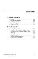 4
4 -
 5
5 -
 6
6 -
 7
7 -
8
-
9
-
10
-
11
-
12
-
13
-
14
-
15
-
16
-
17
-
18
-
19
-
20
-
21
-
22
-
23
-
24
-
25
-
26
-
27
-
28
-
29
-
30
-
31
-
32
-
33
-
34
-
35
-
36
-
37
-
38
-
39
-
40
-
41
-
42
-
43
-
44
-
45
-
46
-
47
-
48
-
49
-
50
-
51
-
52
-
53
-
54
-
55
-
56
-
57
-
58
-
59
-
60
-
61
-
62
-
63
-
64
-
65
-
66
-
67
-
68
-
69
-
70
-
71
-
72
-
73
-
74
-
75
-
76
-
77
-
78
-
79
-
80
-
81
-
82
-
83
-
84
-
85
-
86
-
87
-
88
-
89
-
90
-
91
-
92
-
93
-
94
-
95
-
96
-
97
-
98
-
99
-
100
-
101
-
102
-
103
-
104
-
105
-
106
-
107
-
108
-
109
-
110
-
111
-
112
-
113
-
114
-
115
-
116
-
117
-
118
-
119
-
120
-
121
-
122
-
123
-
124
-
125
-
126
-
127
-
128
-
129
-
130
-
131
-
132
-
133
-
134
-
135
-
136
-
137
-
138
-
139
-
140
-
141
-
142
-
143
-
144
-
145
-
146
-
147
-
148
-
149
-
150
-
151
-
152
-
153
-
154
-
155
-
156
-
157
-
158
-
159
-
160
-
161
-
162
-
163
-
164
-
165
-
166
-
167
-
168
-
169
-
170
-
171
-
172
-
173
-
174
-
175
-
176
-
177
-
178
-
179
-
180
-
181
-
182
-
183
-
184
-
185
-
186
-
187
-
188
-
189
-
190
-
191
-
192
-
193
-
194
-
195
-
196
-
197
-
198
-
199
-
200
-
201
-
202
-
203
-
204
-
205
-
206
-
207
-
208
-
209
-
210
-
211
-
212
-
213
-
214
-
215
-
216
-
217
-
218
-
219
-
220
-
221
-
222
-
223
-
224
-
225
-
226
-
227
-
228
-
229
-
230
-
231
-
232
-
233
-
234
-
235
-
236
-
237
-
238
-
239
-
240
-
241
-
242
-
243
-
244
-
245
-
246
-
247
-
248
-
249
-
250
-
251
-
252
-
253
-
254
-
255
-
256
-
257
-
258
-
259
-
260
-
261
-
262
-
263
-
264
-
265
-
266
-
267
 |
 |

Maintenance and Service
Guide
HP Compaq nc6400 Notebook PC
Document Part Number: 406847-003
March 2007
This guide is a troubleshooting reference used for maintaining
and servicing the computer. It provides comprehensive
information on identifying computer features, components, and
spare parts; troubleshooting computer problems; and performing
computer disassembly procedures.