HP Nc6400 HP Compaq nc6400 Notebook PC Maintenance and Service Guide - Page 135
Switch Cover, Switch Cover Spare Part Number Information
 |
View all HP Nc6400 manuals
Add to My Manuals
Save this manual to your list of manuals |
Page 135 highlights
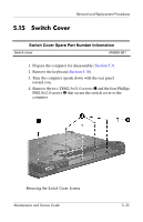
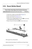
Removal and Replacement Procedures 5.15 Switch Cover Switch Cover Spare Part Number Information Switch cover 418900-001 1. Prepare the computer for disassembly (Section 5.3). 2. Remove the keyboard (Section 5.10). 3. Turn the computer upside down with the rear panel toward you. 4. Remove the two T8M2.5×11.0 screws 1 and the four Phillips PM2.0×2.0 screws 2 that secure the switch cover to the computer. Removing the Switch Cover Screws Maintenance and Service Guide 5-35
-
 1
1 -
2
-
3
-
4
-
5
-
6
-
7
-
8
-
9
-
10
-
11
-
12
-
13
-
14
-
15
-
16
-
17
-
18
-
19
-
20
-
21
-
22
-
23
-
24
-
25
-
26
-
27
-
28
-
29
-
30
-
31
-
32
-
33
-
34
-
35
-
36
-
37
-
38
-
39
-
40
-
41
-
42
-
43
-
44
-
45
-
46
-
47
-
48
-
49
-
50
-
51
-
52
-
53
-
54
-
55
-
56
-
57
-
58
-
59
-
60
-
61
-
62
-
63
-
64
-
65
-
66
-
67
-
68
-
69
-
70
-
71
-
72
-
73
-
74
-
75
-
76
-
77
-
78
-
79
-
80
-
81
-
82
-
83
-
84
-
85
-
86
-
87
-
88
-
89
-
90
-
91
-
92
-
93
-
94
-
95
-
96
-
97
-
98
-
99
-
100
-
101
-
102
-
103
-
104
-
105
-
106
-
107
-
108
-
109
-
110
-
111
-
112
-
113
-
114
-
115
-
116
-
117
-
118
-
119
-
120
-
121
-
122
-
123
-
124
-
125
-
126
-
127
-
128
-
129
-
 130
130 -
 131
131 -
 132
132 -
 133
133 -
 134
134 -
 135
135 -
 136
136 -
 137
137 -
 138
138 -
 139
139 -
 140
140 -
141
-
142
-
143
-
144
-
145
-
146
-
147
-
148
-
149
-
150
-
151
-
152
-
153
-
154
-
155
-
156
-
157
-
158
-
159
-
160
-
161
-
162
-
163
-
164
-
165
-
166
-
167
-
168
-
169
-
170
-
171
-
172
-
173
-
174
-
175
-
176
-
177
-
178
-
179
-
180
-
181
-
182
-
183
-
184
-
185
-
186
-
187
-
188
-
189
-
190
-
191
-
192
-
193
-
194
-
195
-
196
-
197
-
198
-
199
-
200
-
201
-
202
-
203
-
204
-
205
-
206
-
207
-
208
-
209
-
210
-
211
-
212
-
213
-
214
-
215
-
216
-
217
-
218
-
219
-
220
-
221
-
222
-
223
-
224
-
225
-
226
-
227
-
228
-
229
-
230
-
231
-
232
-
233
-
234
-
235
-
236
-
237
-
238
-
239
-
240
-
241
-
242
-
243
-
244
-
245
-
246
-
247
-
248
-
249
-
250
-
251
-
252
-
253
-
254
-
255
-
256
-
257
-
258
-
259
-
260
-
261
-
262
-
263
-
264
-
265
-
266
-
267
 |
 |

Removal and Replacement Procedures
Maintenance and Service Guide
5°35
5.15
Switch Cover
1. Prepare the computer for disassembly (
Section 5.3
).
2. Remove the keyboard (
Section 5.10
).
3. Turn the computer upside down with the rear panel
toward you.
4.
Remove the two T8M2.5×11.0 screws
1
and the four Phillips
PM2.0×2.0 screws
2
that secure the switch cover to the
computer.
Removing the Switch Cover Screws
Switch Cover Spare Part Number Information
Switch cover
418900-001