HP Nc6400 HP Compaq nc6400 Notebook PC Maintenance and Service Guide - Page 140
Phillips PM2.0×10.0 screws, from the base enclosure.
 |
View all HP Nc6400 manuals
Add to My Manuals
Save this manual to your list of manuals |
Page 140 highlights
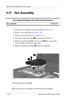
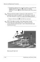
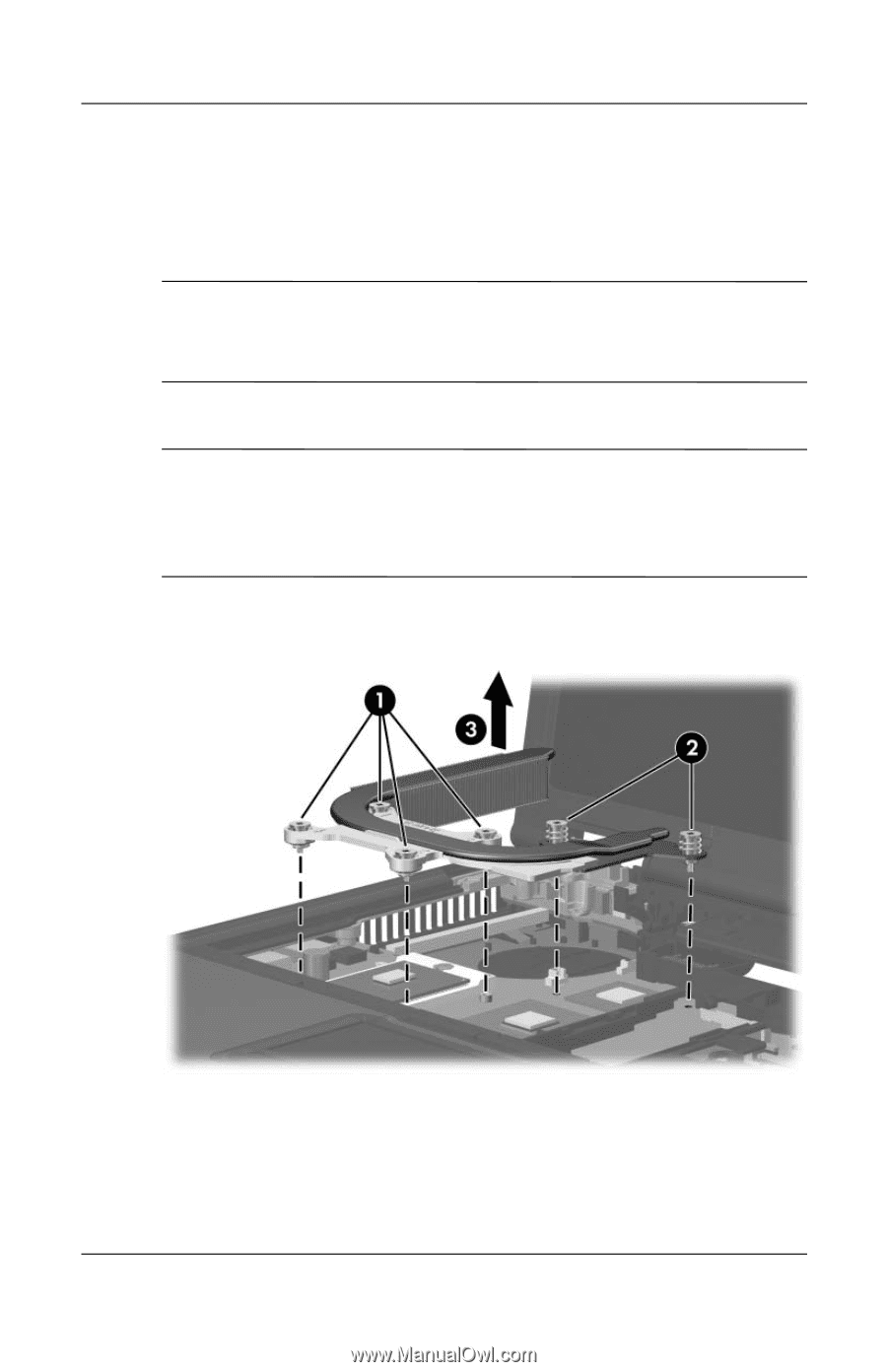
Removal and Replacement Procedures 2. Noting the required screw removal sequence, loosen the four Phillips PM2.0×10.0 screws 1 and the two Phillips PM2.0×13.0 screws 2 that secure the heat sink to the system board. ✎ The heat sink has numbers stamped on it that indicate the required screw removal sequence. You must remove screws in the order indicated to avoid over torque and binding problems. 3. Remove the heat sink 3 from the base enclosure. ✎ Due to the adhesive quality of the thermal paste located between the heat sink and processor, it may be necessary to move the heat sink from side to side to detach the heat sink from the processor. Removing the Heat Sink 5-40 Maintenance and Service Guide
-
 1
1 -
2
-
3
-
4
-
5
-
6
-
7
-
8
-
9
-
10
-
11
-
12
-
13
-
14
-
15
-
16
-
17
-
18
-
19
-
20
-
21
-
22
-
23
-
24
-
25
-
26
-
27
-
28
-
29
-
30
-
31
-
32
-
33
-
34
-
35
-
36
-
37
-
38
-
39
-
40
-
41
-
42
-
43
-
44
-
45
-
46
-
47
-
48
-
49
-
50
-
51
-
52
-
53
-
54
-
55
-
56
-
57
-
58
-
59
-
60
-
61
-
62
-
63
-
64
-
65
-
66
-
67
-
68
-
69
-
70
-
71
-
72
-
73
-
74
-
75
-
76
-
77
-
78
-
79
-
80
-
81
-
82
-
83
-
84
-
85
-
86
-
87
-
88
-
89
-
90
-
91
-
92
-
93
-
94
-
95
-
96
-
97
-
98
-
99
-
100
-
101
-
102
-
103
-
104
-
105
-
106
-
107
-
108
-
109
-
110
-
111
-
112
-
113
-
114
-
115
-
116
-
117
-
118
-
119
-
120
-
121
-
122
-
123
-
124
-
125
-
126
-
127
-
128
-
129
-
130
-
131
-
132
-
133
-
134
-
 135
135 -
 136
136 -
 137
137 -
 138
138 -
 139
139 -
 140
140 -
 141
141 -
 142
142 -
 143
143 -
 144
144 -
 145
145 -
146
-
147
-
148
-
149
-
150
-
151
-
152
-
153
-
154
-
155
-
156
-
157
-
158
-
159
-
160
-
161
-
162
-
163
-
164
-
165
-
166
-
167
-
168
-
169
-
170
-
171
-
172
-
173
-
174
-
175
-
176
-
177
-
178
-
179
-
180
-
181
-
182
-
183
-
184
-
185
-
186
-
187
-
188
-
189
-
190
-
191
-
192
-
193
-
194
-
195
-
196
-
197
-
198
-
199
-
200
-
201
-
202
-
203
-
204
-
205
-
206
-
207
-
208
-
209
-
210
-
211
-
212
-
213
-
214
-
215
-
216
-
217
-
218
-
219
-
220
-
221
-
222
-
223
-
224
-
225
-
226
-
227
-
228
-
229
-
230
-
231
-
232
-
233
-
234
-
235
-
236
-
237
-
238
-
239
-
240
-
241
-
242
-
243
-
244
-
245
-
246
-
247
-
248
-
249
-
250
-
251
-
252
-
253
-
254
-
255
-
256
-
257
-
258
-
259
-
260
-
261
-
262
-
263
-
264
-
265
-
266
-
267
 |
 |
5°40
Maintenance and Service Guide
Removal and Replacement Procedures
2. Noting the required screw removal sequence, loosen the four
Phillips PM2.0×10.0 screws
1
and the two Phillips
PM2.0×13.0 screws
2
that secure the heat sink to the system
board.
✎
The heat sink has numbers stamped on it that indicate the
required screw removal sequence. You must remove screws in
the order indicated to avoid over torque and binding problems.
3. Remove the heat sink
3
from the base enclosure.
✎
Due to the adhesive quality of the thermal paste located
between the heat sink and processor, it may be necessary
to move the heat sink from side to side to detach the heat sink
from the processor.
Removing the Heat Sink