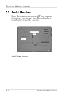
HP Nc6400 HP Compaq nc6400 Notebook PC Maintenance and Service Guide - Page 104
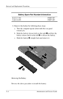
Description, of Screws Removed - memory replacement
 |
View all HP Nc6400 manuals
Add to My Manuals
Save this manual to your list of manuals |
Page 104 highlights
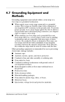
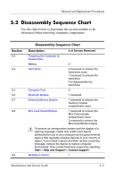
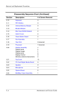
Removal and Replacement Procedures Disassembly Sequence Chart (Continued) Section 5.10 5.11 5.12 5.13 5.14 5.15 5.16 5.17 5.18 5.19 5.20 5.21 5.22 5.23 5.24 5.25 5.26 Description Keyboard RTC Battery Internal Memory Module Modem Module Mini Card WWAN Module Switch Cover Power Button Board Fan Assembly Heat Sink Processor Display Assembly Display bezel Display hinges Display panel Display inverter Wireless antenna transceivers Top Cover PC Card/Digital Media Board Speaker Microphone System Board MultiBay II Eject Assembly # of Screws Removed 3 0 0 2 2 6 2 1 6 loosened 1 loosened 7 4 4 6 0 2 12 3 0 0 6 1 5-4 Maintenance and Service Guide
-
 1
1 -
2
-
3
-
4
-
5
-
6
-
7
-
8
-
9
-
10
-
11
-
12
-
13
-
14
-
15
-
16
-
17
-
18
-
19
-
20
-
21
-
22
-
23
-
24
-
25
-
26
-
27
-
28
-
29
-
30
-
31
-
32
-
33
-
34
-
35
-
36
-
37
-
38
-
39
-
40
-
41
-
42
-
43
-
44
-
45
-
46
-
47
-
48
-
49
-
50
-
51
-
52
-
53
-
54
-
55
-
56
-
57
-
58
-
59
-
60
-
61
-
62
-
63
-
64
-
65
-
66
-
67
-
68
-
69
-
70
-
71
-
72
-
73
-
74
-
75
-
76
-
77
-
78
-
79
-
80
-
81
-
82
-
83
-
84
-
85
-
86
-
87
-
88
-
89
-
90
-
91
-
92
-
93
-
94
-
95
-
96
-
97
-
98
-
 99
99 -
 100
100 -
 101
101 -
 102
102 -
 103
103 -
 104
104 -
 105
105 -
 106
106 -
 107
107 -
 108
108 -
 109
109 -
110
-
111
-
112
-
113
-
114
-
115
-
116
-
117
-
118
-
119
-
120
-
121
-
122
-
123
-
124
-
125
-
126
-
127
-
128
-
129
-
130
-
131
-
132
-
133
-
134
-
135
-
136
-
137
-
138
-
139
-
140
-
141
-
142
-
143
-
144
-
145
-
146
-
147
-
148
-
149
-
150
-
151
-
152
-
153
-
154
-
155
-
156
-
157
-
158
-
159
-
160
-
161
-
162
-
163
-
164
-
165
-
166
-
167
-
168
-
169
-
170
-
171
-
172
-
173
-
174
-
175
-
176
-
177
-
178
-
179
-
180
-
181
-
182
-
183
-
184
-
185
-
186
-
187
-
188
-
189
-
190
-
191
-
192
-
193
-
194
-
195
-
196
-
197
-
198
-
199
-
200
-
201
-
202
-
203
-
204
-
205
-
206
-
207
-
208
-
209
-
210
-
211
-
212
-
213
-
214
-
215
-
216
-
217
-
218
-
219
-
220
-
221
-
222
-
223
-
224
-
225
-
226
-
227
-
228
-
229
-
230
-
231
-
232
-
233
-
234
-
235
-
236
-
237
-
238
-
239
-
240
-
241
-
242
-
243
-
244
-
245
-
246
-
247
-
248
-
249
-
250
-
251
-
252
-
253
-
254
-
255
-
256
-
257
-
258
-
259
-
260
-
261
-
262
-
263
-
264
-
265
-
266
-
267
 |
 |
5°4
Maintenance and Service Guide
Removal and Replacement Procedures
Section
Description
# of Screws Removed
5.10
Keyboard
3
5.11
RTC Battery
0
5.12
Internal Memory Module
0
5.13
Modem Module
2
5.14
Mini Card WWAN Module
2
5.15
Switch Cover
6
5.16
Power Button Board
2
5.17
Fan Assembly
1
5.18
Heat Sink
6 loosened
5.19
Processor
1 loosened
5.20
Display Assembly
Display bezel
Display hinges
Display panel
Display inverter
Wireless antenna transceivers
7
4
4
6
0
2
5.21
Top Cover
12
5.22
PC Card/Digital Media Board
3
5.23
Speaker
0
5.24
Microphone
0
5.25
System Board
6
5.26
MultiBay II Eject Assembly
1
Disassembly Sequence Chart
(Continued)