HP Nc6400 HP Compaq nc6400 Notebook PC Maintenance and Service Guide - Page 155
Top Cover, Top Cover Spare Part Number Information
 |
View all HP Nc6400 manuals
Add to My Manuals
Save this manual to your list of manuals |
Page 155 highlights
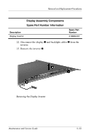
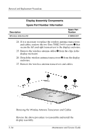
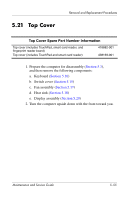
5.21 Top Cover Removal and Replacement Procedures Top Cover Spare Part Number Information Top cover (includes TouchPad, smart card reader, and fingerprint reader board) Top cover (includes TouchPad and smart card reader) 418882-001 438169-001 1. Prepare the computer for disassembly (Section 5.3), and then remove the following components: a. Keyboard (Section 5.10) b. Switch cover (Section 5.15) c. Fan assembly (Section 5.17) d. Heat sink (Section 5.18) e. Display assembly (Section 5.20) 2. Turn the computer upside down with the front toward you. Maintenance and Service Guide 5-55
-
 1
1 -
2
-
3
-
4
-
5
-
6
-
7
-
8
-
9
-
10
-
11
-
12
-
13
-
14
-
15
-
16
-
17
-
18
-
19
-
20
-
21
-
22
-
23
-
24
-
25
-
26
-
27
-
28
-
29
-
30
-
31
-
32
-
33
-
34
-
35
-
36
-
37
-
38
-
39
-
40
-
41
-
42
-
43
-
44
-
45
-
46
-
47
-
48
-
49
-
50
-
51
-
52
-
53
-
54
-
55
-
56
-
57
-
58
-
59
-
60
-
61
-
62
-
63
-
64
-
65
-
66
-
67
-
68
-
69
-
70
-
71
-
72
-
73
-
74
-
75
-
76
-
77
-
78
-
79
-
80
-
81
-
82
-
83
-
84
-
85
-
86
-
87
-
88
-
89
-
90
-
91
-
92
-
93
-
94
-
95
-
96
-
97
-
98
-
99
-
100
-
101
-
102
-
103
-
104
-
105
-
106
-
107
-
108
-
109
-
110
-
111
-
112
-
113
-
114
-
115
-
116
-
117
-
118
-
119
-
120
-
121
-
122
-
123
-
124
-
125
-
126
-
127
-
128
-
129
-
130
-
131
-
132
-
133
-
134
-
135
-
136
-
137
-
138
-
139
-
140
-
141
-
142
-
143
-
144
-
145
-
146
-
147
-
148
-
149
-
 150
150 -
 151
151 -
 152
152 -
 153
153 -
 154
154 -
 155
155 -
 156
156 -
 157
157 -
 158
158 -
 159
159 -
 160
160 -
161
-
162
-
163
-
164
-
165
-
166
-
167
-
168
-
169
-
170
-
171
-
172
-
173
-
174
-
175
-
176
-
177
-
178
-
179
-
180
-
181
-
182
-
183
-
184
-
185
-
186
-
187
-
188
-
189
-
190
-
191
-
192
-
193
-
194
-
195
-
196
-
197
-
198
-
199
-
200
-
201
-
202
-
203
-
204
-
205
-
206
-
207
-
208
-
209
-
210
-
211
-
212
-
213
-
214
-
215
-
216
-
217
-
218
-
219
-
220
-
221
-
222
-
223
-
224
-
225
-
226
-
227
-
228
-
229
-
230
-
231
-
232
-
233
-
234
-
235
-
236
-
237
-
238
-
239
-
240
-
241
-
242
-
243
-
244
-
245
-
246
-
247
-
248
-
249
-
250
-
251
-
252
-
253
-
254
-
255
-
256
-
257
-
258
-
259
-
260
-
261
-
262
-
263
-
264
-
265
-
266
-
267
 |
 |

Removal and Replacement Procedures
Maintenance and Service Guide
5°55
5.21
Top Cover
1. Prepare the computer for disassembly (
Section 5.3
),
and then remove the following components:
a.
Keyboard (
Section 5.10
)
b.
Switch cover (
Section 5.15
)
c.
Fan assembly (
Section 5.17
)
d.
Heat sink (
Section 5.18
)
e.
Display assembly (
Section 5.20
)
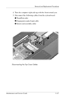
2. Turn the computer upside down with the front toward you.
Top Cover Spare Part Number Information
Top cover (includes TouchPad, smart card reader, and
fingerprint reader board)
Top cover (includes TouchPad and smart card reader)
418882-001
438169-001