HP Pro Tower 200 G9 Desktop PC Maintenance and Service Guide - Page 33
Hard drive, package Fragile: Handle With Care.
 |
View all HP Pro Tower 200 G9 Desktop PC manuals
Add to My Manuals
Save this manual to your list of manuals |
Page 33 highlights
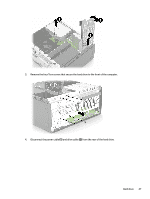
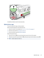
To install the front bezel, reverse the removal procedure. Hard drive To remove a hard drive, use these procedures. ● The primary Serial ATA (SATA) hard drive must be connected to the dark-blue primary SATA connector labeled SATA0 on the system board. ● Connect an optical drive to the connector on the system board labeled SATA1. IMPORTANT: To prevent loss of work and damage to the computer or drive: If you are inserting or removing a drive, shut down the operating system properly, turn off the computer, and unplug the power cord. Do not remove a drive while the computer is on or in standby mode. Before handling a drive, be sure that you are discharged of static electricity. While handling a drive, avoid touching the connector. Handle a drive carefully; do not drop it. Do not use excessive force when inserting a drive. Avoid exposing a hard drive to liquids, temperature extremes, or products that have magnetic fields such as monitors or speakers. If a drive must be mailed, place the drive in a bubble-pack mailer or other protective packaging and label the package "Fragile: Handle With Care." Before removing the hard drive, follow these steps: 1. Prepare the computer for disassembly (see Preparation for disassembly on page 17). 2. Remove the access panel (see Access panel on page 17). 3. Remove the optical drive (see Optical drive on page 24). 4. Remove the front bezel (see Front bezel on page 25). Remove the hard drive: 1. Remove the Torx screw (1) that secures the drive cage to the computer. 2. Rotate the drive cage upright (2) and then remove it from the computer (3). NOTE: Computer appearance might vary. 26 Chapter 4 Removal and replacement procedures
-
 1
1 -
2
-
3
-
4
-
5
-
6
-
7
-
8
-
9
-
10
-
11
-
12
-
13
-
14
-
15
-
16
-
17
-
18
-
19
-
20
-
21
-
22
-
23
-
24
-
25
-
26
-
27
-
 28
28 -
 29
29 -
 30
30 -
 31
31 -
 32
32 -
 33
33 -
 34
34 -
 35
35 -
 36
36 -
 37
37 -
 38
38 -
39
-
40
-
41
-
42
-
43
-
44
-
45
-
46
-
47
-
48
-
49
-
50
-
51
-
52
-
53
-
54
-
55
-
56
-
57
-
58
-
59
-
60
-
61
-
62
-
63
-
64
-
65
-
66
-
67
-
68
-
69
-
70
-
71
-
72
-
73
-
74
-
75
-
76
-
77
-
78
-
79
-
80
-
81
-
82
-
83
-
84
-
85
-
86
-
87
-
88
-
89
-
90
-
91
-
92
-
93
-
94
-
95
-
96
-
97
-
98
-
99
-
100
-
101
-
102
-
103
-
104
-
105
-
106
-
107
-
108
-
109
-
110
-
111
-
112
-
113
-
114
-
115
-
116
 |
 |
