HP Pro Tower 200 G9 Desktop PC Maintenance and Service Guide - Page 42
Processor, For a list of available processors, see
 |
View all HP Pro Tower 200 G9 Desktop PC manuals
Add to My Manuals
Save this manual to your list of manuals |
Page 42 highlights
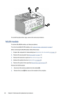
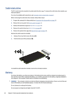
1. Loosen the four captive Torx screws (1) that secure the fan sink to the system board tray. IMPORTANT: Remove heat sink retaining screws in diagonally opposite pairs (as in an X) to evenly apply the downward forces on the processor. The pins on the socket are fragile, and any damage to them could require replacing the system board. 2. Disconnect the fan cable from the system board (2). 3. Lift the fan sink from the processor (3). NOTE: Computer appearance might vary. 4. Thoroughly clean the thermal material from the surfaces of the heat sink and the system board components each time the heat sink is removed. Replacement thermal material is included with the heat sink and system board spare part kits. IMPORTANT: Tighten heat sink retaining screws in diagonally opposite pairs (as in an X) to evenly seat the heat sink on the processor to avoid damage that could require replacing the system board. To replace the heat sink with fan, reverse the removal procedures. Processor To remove the processor, use these procedures. For a list of available processors, see Computer major components on page 4. Before removing the processor, follow these steps: 1. Prepare the computer for disassembly (see Preparation for disassembly on page 17). 2. Remove the access panel (see Access panel on page 17). 3. Remove the heat sink with fan (see Heat sink with fan on page 34). Remove the processor: Processor 35
-
 1
1 -
2
-
3
-
4
-
5
-
6
-
7
-
8
-
9
-
10
-
11
-
12
-
13
-
14
-
15
-
16
-
17
-
18
-
19
-
20
-
21
-
22
-
23
-
24
-
25
-
26
-
27
-
28
-
29
-
30
-
31
-
32
-
33
-
34
-
35
-
36
-
 37
37 -
 38
38 -
 39
39 -
 40
40 -
 41
41 -
 42
42 -
 43
43 -
 44
44 -
 45
45 -
 46
46 -
 47
47 -
48
-
49
-
50
-
51
-
52
-
53
-
54
-
55
-
56
-
57
-
58
-
59
-
60
-
61
-
62
-
63
-
64
-
65
-
66
-
67
-
68
-
69
-
70
-
71
-
72
-
73
-
74
-
75
-
76
-
77
-
78
-
79
-
80
-
81
-
82
-
83
-
84
-
85
-
86
-
87
-
88
-
89
-
90
-
91
-
92
-
93
-
94
-
95
-
96
-
97
-
98
-
99
-
100
-
101
-
102
-
103
-
104
-
105
-
106
-
107
-
108
-
109
-
110
-
111
-
112
-
113
-
114
-
115
-
116
 |
 |
