HP ProBook 5330m HP ProBook 5330m Notebook PC - Maintenance and Service Guide
HP ProBook 5330m Manual
 |
View all HP ProBook 5330m manuals
Add to My Manuals
Save this manual to your list of manuals |
HP ProBook 5330m manual content summary:
- HP ProBook 5330m | HP ProBook 5330m Notebook PC - Maintenance and Service Guide - Page 1
HP ProBook 5330m Notebook PC Maintenance and Service Guide SUMMARY This guide is a troubleshooting reference used for maintaining and servicing the computer. It provides comprehensive information on identifying computer features, components, and spare parts; troubleshooting computer problems; and - HP ProBook 5330m | HP ProBook 5330m Notebook PC - Maintenance and Service Guide - Page 2
to change without notice. The only warranties for HP products and services are set forth in the express warranty statements accompanying such products and services. Nothing herein should be construed as constituting an additional warranty. HP shall not be liable for technical or editorial errors - HP ProBook 5330m | HP ProBook 5330m Notebook PC - Maintenance and Service Guide - Page 3
Safety warning notice WARNING! To reduce the possibility of heat-related injuries or of overheating the computer, do not place the computer directly on your lap or obstruct the computer air vents. Use the computer only on a hard, flat surface. Do not allow another hard surface, such as an adjoining - HP ProBook 5330m | HP ProBook 5330m Notebook PC - Maintenance and Service Guide - Page 4
iv Safety warning notice - HP ProBook 5330m | HP ProBook 5330m Notebook PC - Maintenance and Service Guide - Page 5
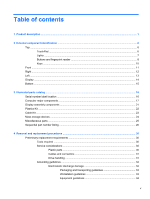
25 Sequential part number listing ...26 4 Removal and replacement procedures ...30 Preliminary replacement requirements 30 Tools required ...30 Service considerations ...30 Plastic parts ...30 Cables and connectors 31 Drive handling 31 Grounding guidelines ...32 Electrostatic discharge damage 32 - HP ProBook 5330m | HP ProBook 5330m Notebook PC - Maintenance and Service Guide - Page 6
Component replacement procedures 35 Service tag ...35 Battery ...36 Service access cover ...38 SIM ...39 Memory module ...40 WLAN module ...41 WWAN module ...44 Hard drive ...47 Keyboard ...50 Fan ...53 Top cover ...55 Power - HP ProBook 5330m | HP ProBook 5330m Notebook PC - Maintenance and Service Guide - Page 7
Security menu 90 System Configuration menu 90 Computer Setup in Linux ...94 Starting Computer Setup 94 Using Computer Setup ...94 Navigating and selecting in Computer Setup 94 Restoring factory settings in Computer Setup 95 Computer Setup menus ...95 File menu ...95 Security menu 96 - HP ProBook 5330m | HP ProBook 5330m Notebook PC - Maintenance and Service Guide - Page 8
Index ...118 viii - HP ProBook 5330m | HP ProBook 5330m Notebook PC - Maintenance and Service Guide - Page 9
description Category Product Name Processors Chipset Graphics Panels Memory Hard drives Description HP ProBook 5330m Notebook PC Intel® Core™ processors ● Intel Core i3-2310M, Dual- video memory (dynamically allocated) All display panel assemblies support privacy filter LED backlight 33.8 cm (13.3 - HP ProBook 5330m | HP ProBook 5330m Notebook PC - Maintenance and Service Guide - Page 10
● 500 GB, 7200-rpm ● 320 GB Self-Encrypting Drive (SED), 7200-rpm ● 320 GB, 7200-rpm ● 250 GB, 7200-rpm Supports the following solid-state drive: ● 128 GB HP 3D DriveGuard (not available with Linux) Beats audio Integrated microphone (dual-array) Two stereo speakers Integrated 720p webcam 10/100/1000 - HP ProBook 5330m | HP ProBook 5330m Notebook PC - Maintenance and Service Guide - Page 11
(3-wire plug with ground pin) 4-cell, 41-Wh 2.8-Ah Li-ion battery Supports security lock Intel AT support Integrated fingerprint reader Full volume encryption TPM 100% attach HP face recognition Privacy filter Preboot authentication (password, smart card) Preinstalled operating systems: ● Windows - HP ProBook 5330m | HP ProBook 5330m Notebook PC - Maintenance and Service Guide - Page 12
Category Description Preinstalled Windows operating systems, plus Microsoft® Office: ● Windows Vista Home Basic 32-bit with Office Starter (excludes Japan, selected localizations only) ● Windows 7 Home Basic 32-bit with Office Starter (selected localizations only) ● Windows 7 Home Basic 64-bit with - HP ProBook 5330m | HP ProBook 5330m Notebook PC - Maintenance and Service Guide - Page 13
Category Serviceability Description Web-only support: ● Windows XP Professional 32-bit ● Windows 7 Enterprise 32/64 ● Windows 7 Ultimate End-user replaceable parts: ● Battery (system) ● Memory module ● WLAN module ● WWAN module ● Hard drive ● Keyboard 5 - HP ProBook 5330m | HP ProBook 5330m Notebook PC - Maintenance and Service Guide - Page 14
2 External component identification Top TouchPad Component (1) (2) TouchPad on/off button TouchPad (3) Left TouchPad button (4) Right TouchPad button Description Turns the TouchPad on and off. Moves the pointer and selects or activates items on the screen. Functions like the left button on an - HP ProBook 5330m | HP ProBook 5330m Notebook PC - Maintenance and Service Guide - Page 15
on. ● Blinking (in Linux): The Web browser is loading. ● Off: The computer is off or in Hibernation. NOTE: For more Windows information, refer to the HP QuickWeb software Help. ● Amber: Computer sound is off. ● Off: Computer sound is on. On: Caps lock is on. ● Amber: The TouchPad is off. ● Off: The - HP ProBook 5330m | HP ProBook 5330m Notebook PC - Maintenance and Service Guide - Page 16
> System and Security > Power Options. - or - Windows Vista-Select Start > Control Panel > System and Maintenance > Power Options. ● Refer to the HP Notebook Reference Guide. - or - Linux-Select Computer > Control Center. In the left pane, click System, and then click Power Management in the right - HP ProBook 5330m | HP ProBook 5330m Notebook PC - Maintenance and Service Guide - Page 17
feature on or off but does not establish a wireless connection. In Windows: ● When the computer is off or in Hibernation, press the button to open HP QuickWeb. ● When the computer is in Microsoft Windows, press the button to open the default Web browser. ● When the computer is in - HP ProBook 5330m | HP ProBook 5330m Notebook PC - Maintenance and Service Guide - Page 18
Keys Component (1) esc key (2) fn key (3) Windows logo key (4) Function keys (5) Windows applications key (6) Embedded numeric keypad (7) num lk key Description In Windows, displays system information when pressed in combination with the fn key. In Windows, executes frequently used - HP ProBook 5330m | HP ProBook 5330m Notebook PC - Maintenance and Service Guide - Page 19
(Suspend in Linux) state. ● Off: The computer is off or in Hibernation. ● Blinking white: The hard drive is being accessed. ● Amber: HP 3D DriveGuard has temporarily parked the hard drive. NOTE: For information on HP 3D DriveGuard, refer to the HP Notebook Reference Guide. Produce sound. Front 11 - HP ProBook 5330m | HP ProBook 5330m Notebook PC - Maintenance and Service Guide - Page 20
: When a device is connected to the jack, the computer speakers are disabled. NOTE: Be sure that the device cable has a 4-conductor connector that supports both audio-out (headphone) and audio in (microphone). Connects an optional USB device and can also charge select models of cell phones and MP3 - HP ProBook 5330m | HP ProBook 5330m Notebook PC - Maintenance and Service Guide - Page 21
, or connects an optional USB device. Connects an optional video or audio device, such as a high-definition television, or any compatible digital or audio component. Supports the following digital card formats: ● MultiMediaCard ● Secure Digital (SD) Memory Card Left 13 - HP ProBook 5330m | HP ProBook 5330m Notebook PC - Maintenance and Service Guide - Page 22
and captures still photographs. To use the webcam: ● In Windows, select Start > All Programs > HP > HP Webcam. ● In Linux, select Computer > More Applications > Cheese. *The antennas are not visible . These notices are located in Help and Support. 14 Chapter 2 External component identification - HP ProBook 5330m | HP ProBook 5330m Notebook PC - Maintenance and Service Guide - Page 23
. It is normal for the internal fan to cycle on and off during routine operation. Bluetooth compartment Contains a Bluetooth device. SIM slot Supports a wireless subscriber identity module (SIM). The SIM slot is located inside the battery bay. Hard drive bay and wireless and memory module - HP ProBook 5330m | HP ProBook 5330m Notebook PC - Maintenance and Service Guide - Page 24
provides important information that you may need when contacting technical support. Component Description (1) Product name The product name affixed about the product's hardware components. The part number helps a service technician to determine what components and parts are needed. (4) - HP ProBook 5330m | HP ProBook 5330m Notebook PC - Maintenance and Service Guide - Page 25
Computer major components Computer major components 17 - HP ProBook 5330m | HP ProBook 5330m Notebook PC - Maintenance and Service Guide - Page 26
Item Description Spare part number (1) 33.8 cm (13.3 in) HD AntiGlare LED display (1280x800) 650397-001 NOTE: The WLAN antennas and cables and the WWAN antennas and cables are included in the Antenna Kit, spare part number 650365-001. (2) Keyboard ● For use in Adriatic countries ● For use in - HP ProBook 5330m | HP ProBook 5330m Notebook PC - Maintenance and Service Guide - Page 27
Item Description Spare part number (4) Top cover ● With fingerprint reader ● Without fingerprint reader 651761-001 650404-001 (5) Power button board (includes cable) 650392-001 (6) Activity button board (includes cable) 650393-001 (7) Audio board (includes cable) 650394-001 (8) Power - HP ProBook 5330m | HP ProBook 5330m Notebook PC - Maintenance and Service Guide - Page 28
● 250 GB, 7200-rpm 634861-001 Solid-state drive ● 128 GB 650401-001 (20) WWAN module (not available with Linux) HP hs2340 HSPA+ Mobile Broadband Module 632155-001 HP un2430 EV-DO/HSPA Mobile Broadband Module 634400-001 (21) WLAN module Broadcom 4313 802.11b/g/n 1x1 WiFi Adapter for use in - HP ProBook 5330m | HP ProBook 5330m Notebook PC - Maintenance and Service Guide - Page 29
Item Description (23) Service access cover NOTE: The service access cover is included in the Plastics Kit, spare part number 650395-001. See Plastics Kit on page 22 for more Plastics Kit spare part - HP ProBook 5330m | HP ProBook 5330m Notebook PC - Maintenance and Service Guide - Page 30
number 650365-001) (8) Webcam module (9) Display back cover Plastics Kit Spare part number 650376-001 650370-001 650405-001 650366-001 Item Description Plastics Kit: (1) Service access cover (2) Battery cover (3) SD Card blank 22 Chapter 3 Illustrated parts catalog Spare part number 650395-001 - HP ProBook 5330m | HP ProBook 5330m Notebook PC - Maintenance and Service Guide - Page 31
Cable Kit Item (1) (2) (3) Description Cable Kit: Bluetooth cable TouchPad cable Power cable Spare part number 650369-001 Cable Kit 23 - HP ProBook 5330m | HP ProBook 5330m Notebook PC - Maintenance and Service Guide - Page 32
Mass storage devices Item Description (1) Hard drive bracket NOTE: The hard drive bracket is included in the Hard Drive Hardware Kit, spare part number 650373-001. (2) Solid-state drive (128 GB) (3) SATA 6.35-cm (2.5 in) hard drive 9.5 mm hard drives ● 500 GB, 7200-rpm ● 320 GB, 7200-rpm, - HP ProBook 5330m | HP ProBook 5330m Notebook PC - Maintenance and Service Guide - Page 33
Miscellaneous parts Description AC adapters 65 W, 3-pin Smart AC Adapter (for use in all countries and regions except Australia, Bangladesh, Brunei, Cambodia, Hong Kong, India, Indonesia, Japan, Laos, Malaysia, Nepal, New Zealand, Pakistan, the People's Republic of China, the Philippines, Singapore - HP ProBook 5330m | HP ProBook 5330m Notebook PC - Maintenance and Service Guide - Page 34
Sequential part number listing Spare part number 490371-001 490371-011 490371-021 490371-031 490371-061 490371-081 490371-111 490371-201 490371-291 490371-AA1 490371-AB1 490371-AD1 490371-AR1 490371-BB1 490371-D01 490371-D61 537921-001 581096-001 582564-001 582564-002 Description Power cord (AC - HP ProBook 5330m | HP ProBook 5330m Notebook PC - Maintenance and Service Guide - Page 35
, shared), 4096-MB 9.5 mm hard drive, 320 GB, 7200-rpm, Self-Encrypting Intel Centrino® Advanced N 6205 802.11a/b/g/n, 2x2 WiFi Adapter HP hs2340 HSPA+ Mobile Broadband Module HP un2430 EV-DO/HSPA Mobile Broadband Module (select models only) 7 mm hard drive, 250 GB, 7200-rpm 7 mm hard drive, 320 GB - HP ProBook 5330m | HP ProBook 5330m Notebook PC - Maintenance and Service Guide - Page 36
for use in Africa-French/Arabic Power button board with cable Activity button board with cable Audio board (includes cable) Plastics Kit (includes service access cover, battery cover, and SD Card blank) 33.8 cm (13.3 in) HD AntiGlare LED display (1280x800) RTC battery 28 Chapter 3 Illustrated parts - HP ProBook 5330m | HP ProBook 5330m Notebook PC - Maintenance and Service Guide - Page 37
Spare part number 650399-001 650400-001 650401-001 650402-001 650403-001 650404-001 650405-001 651761-001 656796-001 656797-001 Description Screw Kit (See Miscellaneous parts on page 25 for more Screw Kit spare part information.) Speaker assembly Solid-state drive, 6.35 cm (2.5 in), 128 GB System - HP ProBook 5330m | HP ProBook 5330m Notebook PC - Maintenance and Service Guide - Page 38
removal and replacement procedures: ● Flat-bladed screwdriver ● P0 and P1 screwdrivers Service considerations The following sections include some of the considerations that you must keep in only at the points designated in the maintenance instructions. 30 Chapter 4 Removal and replacement procedures - HP ProBook 5330m | HP ProBook 5330m Notebook PC - Maintenance and Service Guide - Page 39
Cables and connectors CAUTION: When servicing the computer, be sure that cables are placed in their proper locations during the reassembly process. Improper cable placement can damage the computer. Cables must - HP ProBook 5330m | HP ProBook 5330m Notebook PC - Maintenance and Service Guide - Page 40
Grounding guidelines Electrostatic discharge damage Electronic components are sensitive to electrostatic discharge (ESD). Circuitry design and structure determine the degree of sensitivity. Networks built into many integrated circuits provide some protection, but in many cases, ESD contains enough - HP ProBook 5330m | HP ProBook 5330m Notebook PC - Maintenance and Service Guide - Page 41
material. ● Use a wrist strap connected to a properly grounded work surface and use properly grounded tools and equipment. ● Use conductive field service tools, such as cutters, screwdrivers, and vacuums. ● When fixtures must directly contact dissipative surfaces, use fixtures made only of static - HP ProBook 5330m | HP ProBook 5330m Notebook PC - Maintenance and Service Guide - Page 42
with ground cords of one megohm resistance ● Static-dissipative tables or floor mats with hard ties to the ground ● Field service kits ● Static awareness labels ● Material-handling packages ● Nonconductive plastic bags, tubes, or boxes ● Metal tote boxes ● Electrostatic voltage levels and - HP ProBook 5330m | HP ProBook 5330m Notebook PC - Maintenance and Service Guide - Page 43
to each product. (3) Product part number The identifier that provides specific information about the product's hardware components. The part number helps a service technician to determine what components and parts are needed. (4) Warranty The duration of the warranty period for this computer - HP ProBook 5330m | HP ProBook 5330m Notebook PC - Maintenance and Service Guide - Page 44
Battery Description 4-cell, 41-Wh (2.8-Ah) Li-on battery Spare part number 635146-001 Before removing the battery, follow these steps: 1. Shut down the computer. If you are unsure whether the computer is off or in Hibernation, turn the computer on, and then shut it down through the operating - HP ProBook 5330m | HP ProBook 5330m Notebook PC - Maintenance and Service Guide - Page 45
6. Then remove the battery from the battery bay (4). Reverse this procedure to install the battery. Component replacement procedures 37 - HP ProBook 5330m | HP ProBook 5330m Notebook PC - Maintenance and Service Guide - Page 46
access cover is included in the Plastics Kit, spare part number 650395-001. Before removing the service access cover, follow these steps: 1. Shut down the computer. If you are unsure whether the computer is off or in Hibernation, turn the computer on, - HP ProBook 5330m | HP ProBook 5330m Notebook PC - Maintenance and Service Guide - Page 47
SIM NOTE: This section applies only to select models with WWAN capability. NOTE: If there is a SIM inserted in the SIM slot, it must be removed before disassembling the computer. Be sure that the SIM is reinserted in the SIM slot after reassembling the computer. Before removing the SIM, follow - HP ProBook 5330m | HP ProBook 5330m Notebook PC - Maintenance and Service Guide - Page 48
the AC outlet and then unplugging the AC adapter from the computer. 4. Remove the battery (see Battery on page 36). 5. Remove the service access cover (see Service access cover on page 38). Remove the memory module: 1. Position the computer upside down with the front toward you. 2. Pull away the - HP ProBook 5330m | HP ProBook 5330m Notebook PC - Maintenance and Service Guide - Page 49
the module to restore computer functionality, and then contact technical support through Help and Support. Before removing the WLAN module, follow these steps: the battery (see Battery on page 36). 5. Remove the service access cover (see Service access cover on page 38). Remove the WLAN module: 1. - HP ProBook 5330m | HP ProBook 5330m Notebook PC - Maintenance and Service Guide - Page 50
2. Remove the protective sleeves from the WLAN antennas. 3. Disconnect the WLAN antenna cables from the terminals on the WLAN module. NOTE: The black WLAN antenna cable is connected to the WLAN module "Main" terminal. The white WLAN antenna cable is connected to the WLAN module "Aux" terminal. 42 - HP ProBook 5330m | HP ProBook 5330m Notebook PC - Maintenance and Service Guide - Page 51
4. Remove the Phillips M2.0×3.0 screw that secures the WLAN module to the system board. (The WLAN module tilts up.) 5. Remove the WLAN module (1) by pulling the module away from the slot at an angle. NOTE: WLAN modules are designed with a notch (2) to prevent incorrect insertion. Reverse this - HP ProBook 5330m | HP ProBook 5330m Notebook PC - Maintenance and Service Guide - Page 52
page 1). Description HP hs2340 HSPA+ Mobile Broadband Module HP un2430 EV-DO/ functionality, and then contact technical support through Help and Support. Before removing the WWAN module, see Battery on page 36). 5. Remove the service access cover (see Service access cover on page 38). Remove the - HP ProBook 5330m | HP ProBook 5330m Notebook PC - Maintenance and Service Guide - Page 53
2. Disconnect the WWAN antenna cables from the terminals on the WWAN module. NOTE: The red WWAN antenna cable is connected to the WLAN module "Main" terminal. The blue WWAN antenna cable is connected to the WWAN module "Aux" terminal. 3. Remove the Phillips M2.0×3.0 screw (1) that secures the WWAN - HP ProBook 5330m | HP ProBook 5330m Notebook PC - Maintenance and Service Guide - Page 54
4. Remove the WWAN module (1) by pulling the module away from the slot at an angle. NOTE: WWAN modules are designed with a notch (2) to prevent incorrect insertion. Reverse this procedure to install the WWAN module. 46 Chapter 4 Removal and replacement procedures - HP ProBook 5330m | HP ProBook 5330m Notebook PC - Maintenance and Service Guide - Page 55
the AC outlet and then unplugging the AC adapter from the computer. 4. Remove the battery (see Battery on page 36). 5. Remove the service access cover (see Service access cover on page 38). Remove the hard drive: 1. Position the computer upside down with the front toward you. Component replacement - HP ProBook 5330m | HP ProBook 5330m Notebook PC - Maintenance and Service Guide - Page 56
2. Loosen the three Phillips M10.0x2.5 captive screws that secure the hard drive to the computer. 3. Grasp the tab (1) on the hard drive, pull the hard drive to the left, and then remove the hard drive (2) at an angle. 4. If it is necessary to replace the hard drive bracket, follow these steps: a. - HP ProBook 5330m | HP ProBook 5330m Notebook PC - Maintenance and Service Guide - Page 57
b. Lift the bracket (2) straight up to remove it from the hard drive. Reverse this procedure to reassemble and install the hard drive. Component replacement procedures 49 - HP ProBook 5330m | HP ProBook 5330m Notebook PC - Maintenance and Service Guide - Page 58
Keyboard NOTE: The keyboard spare part kit includes a keyboard cable. Description Keyboard For use in Adriatic countries For use in Africa-French/Arabic For use in Belgium For use in Bulgaria For use in the Czech Republic and Slovakia For use in Denmark For use in France For use in French Canada For - HP ProBook 5330m | HP ProBook 5330m Notebook PC - Maintenance and Service Guide - Page 59
Before removing the keyboard, follow these steps: 1. Shut down the computer. If you are unsure whether the computer is off or in Hibernation, turn the computer on, and then shut it down through the operating system. 2. Disconnect all external devices connected to the computer. 3. Disconnect the - HP ProBook 5330m | HP ProBook 5330m Notebook PC - Maintenance and Service Guide - Page 60
4. Carefully position the open computer on its left side, and then insert a finger into the finger hole in the battery bay, and press on the keyboard until it disengages from the base enclosure. 5. Turn the computer right-side up, with the front toward you. 6. Rotate the keyboard forward until it - HP ProBook 5330m | HP ProBook 5330m Notebook PC - Maintenance and Service Guide - Page 61
from the AC outlet and then unplugging the AC adapter from the computer. 4. Remove the battery (see Battery on page 36). 5. Remove the service access cover (see Service access cover on page 38). 6. Remove the keyboard (see Keyboard on page 50). Remove the fan: 1. Position the computer upside down on - HP ProBook 5330m | HP ProBook 5330m Notebook PC - Maintenance and Service Guide - Page 62
6. Remove the four T8 2.5x3.0 screws (4) from the fan assembly, and then remove the fan assembly (5) from the base enclosure. Reverse this procedure to install the fan assembly. 54 Chapter 4 Removal and replacement procedures - HP ProBook 5330m | HP ProBook 5330m Notebook PC - Maintenance and Service Guide - Page 63
Top cover Description Top cover NOTE: The top cover kit includes the TouchPad assembly. With fingerprint reader Without fingerprint reader Spare part number 651761-001 650404-001 Before removing the top cover, follow these steps: 1. Shut down the computer. If you are unsure whether the computer is - HP ProBook 5330m | HP ProBook 5330m Notebook PC - Maintenance and Service Guide - Page 64
5. Open the activity button cable ZIF connector (7) and disconnect the cable (8). 6. Remove the three T8 2.5x4.0 screws under the keyboard front edge. 56 Chapter 4 Removal and replacement procedures - HP ProBook 5330m | HP ProBook 5330m Notebook PC - Maintenance and Service Guide - Page 65
7. Turn the computer over and remove the four T8 2.5x3.0 screws from the rear of the computer, three T8 2.5x3.0 screws from the hard drive bay, and four T8 2.0x4.0 screws from the front edge of the computer. 8. Turn the computer right-side up, open the display, and then disengage the top cover from - HP ProBook 5330m | HP ProBook 5330m Notebook PC - Maintenance and Service Guide - Page 66
10. Remove the top cover (4). Reverse this procedure to install the top cover. 58 Chapter 4 Removal and replacement procedures - HP ProBook 5330m | HP ProBook 5330m Notebook PC - Maintenance and Service Guide - Page 67
from the AC outlet and then unplugging the AC adapter from the computer. 4. Remove the battery (see Battery on page 36). 5. Remove the service access cover (see Service access cover on page 38). 6. Remove the keyboard (see Keyboard on page 50). 7. Remove the fan (see Fan on page 53). 8. Remove the - HP ProBook 5330m | HP ProBook 5330m Notebook PC - Maintenance and Service Guide - Page 68
from the AC outlet and then unplugging the AC adapter from the computer. 4. Remove the battery (see Battery on page 36). 5. Remove the service access cover (see Service access cover on page 38). 6. Remove the keyboard (see Keyboard on page 50). 7. Remove the fan (see Fan on page 53). 8. Remove the - HP ProBook 5330m | HP ProBook 5330m Notebook PC - Maintenance and Service Guide - Page 69
from the AC outlet and then unplugging the AC adapter from the computer. 4. Remove the battery (see Battery on page 36). 5. Remove the service access cover (see Service access cover on page 38). 6. Remove the keyboard (see Keyboard on page 50). 7. Remove the fan (see Fan on page 53). 8. Remove the - HP ProBook 5330m | HP ProBook 5330m Notebook PC - Maintenance and Service Guide - Page 70
from the AC outlet and then unplugging the AC adapter from the computer. 4. Remove the battery (see Battery on page 36). 5. Remove the service access cover (see Service access cover on page 38). 6. Remove the keyboard (see Keyboard on page 50). 7. Remove the fan (see Fan on page 53). 8. Remove the - HP ProBook 5330m | HP ProBook 5330m Notebook PC - Maintenance and Service Guide - Page 71
4. Disconnect the Bluetooth cable (3) from the Bluetooth module. Reverse this procedure to install the Bluetooth module. Component replacement procedures 63 - HP ProBook 5330m | HP ProBook 5330m Notebook PC - Maintenance and Service Guide - Page 72
from the AC outlet and then unplugging the AC adapter from the computer. 4. Remove the battery (see Battery on page 36). 5. Remove the service access cover (see Service access cover on page 38). 6. Remove the keyboard (see Keyboard on page 50). 7. Remove the fan (see Fan on page 53). 8. Remove the - HP ProBook 5330m | HP ProBook 5330m Notebook PC - Maintenance and Service Guide - Page 73
from the AC outlet and then unplugging the AC adapter from the computer. 4. Remove the battery (see Battery on page 36). 5. Remove the service access cover (see Service access cover on page 38). 6. Remove the keyboard (see Keyboard on page 50). 7. Remove the fan (see Fan on page 53). 8. Remove the - HP ProBook 5330m | HP ProBook 5330m Notebook PC - Maintenance and Service Guide - Page 74
from the AC outlet and then unplugging the AC adapter from the computer. 4. Remove the battery (see Battery on page 36). 5. Remove the service access cover (see Service access cover on page 38). 6. Remove the keyboard (see Keyboard on page 50). 7. Remove the fan (see Fan on page 53). 8. Remove the - HP ProBook 5330m | HP ProBook 5330m Notebook PC - Maintenance and Service Guide - Page 75
2. Remove the three T8 2.5x4.0 screws (marked with triangles) that secure the system board to the base enclosure. 3. Rotate the system board to the right (1). 4. Disconnect the power cable (2) from the system board, and then remove the system board (3). Reverse this procedure to install the system - HP ProBook 5330m | HP ProBook 5330m Notebook PC - Maintenance and Service Guide - Page 76
from the AC outlet and then unplugging the AC adapter from the computer. 4. Remove the battery (see Battery on page 36). 5. Remove the service access cover (see Service access cover on page 38). 6. Remove the keyboard (see Keyboard on page 50). 7. Remove the fan (see Fan on page 53). 8. Remove the - HP ProBook 5330m | HP ProBook 5330m Notebook PC - Maintenance and Service Guide - Page 77
Reverse this procedure to install the heat sink. Component replacement procedures 69 - HP ProBook 5330m | HP ProBook 5330m Notebook PC - Maintenance and Service Guide - Page 78
from the AC outlet and then unplugging the AC adapter from the computer. 4. Remove the battery (see Battery on page 36). 5. Remove the service access cover (see Service access cover on page 38). 6. Remove the keyboard (see Keyboard on page 50). 7. Remove the fan (see Fan on page 53). 8. Remove the - HP ProBook 5330m | HP ProBook 5330m Notebook PC - Maintenance and Service Guide - Page 79
5. Remove the power connector and cable (4) by lifting them straight up from the base enclosure. Reverse this procedure to install the power connector cable. Component replacement procedures 71 - HP ProBook 5330m | HP ProBook 5330m Notebook PC - Maintenance and Service Guide - Page 80
Display panel Description Display bezel 33.8 cm (13.3 in) High-Definition (HD) AntiGlare LED display (1280x800) Spare part number 650368-001 650397-001 NOTE: If you need to remove only the display panel, not the complete display assembly, follow the steps in this section. To remove the complete - HP ProBook 5330m | HP ProBook 5330m Notebook PC - Maintenance and Service Guide - Page 81
5. Remove the display bezel from the display back cover (4). 6. Position the computer with the display assembly on a flat surface and the keyboard open at a 90-degree angle. 7. Disconnect the webcam cable (1) and remove the four Phillips M2.0x3.0 screws (2) that secure the display panel to the hinge - HP ProBook 5330m | HP ProBook 5330m Notebook PC - Maintenance and Service Guide - Page 82
9. Peel the adhesive from the back of the display panel (3), disconnect the display cable (4), and then remove the display panel (5). Reverse this procedure to install the display panel. 74 Chapter 4 Removal and replacement procedures - HP ProBook 5330m | HP ProBook 5330m Notebook PC - Maintenance and Service Guide - Page 83
bezel for access to those components. For display bezel removal instructions, see Display panel on page 72. Before removing the display the display panel (see Display panel on page 72). 6. Remove the service access cover (see Service access cover on page 38). 7. Remove the keyboard (see Keyboard - HP ProBook 5330m | HP ProBook 5330m Notebook PC - Maintenance and Service Guide - Page 84
and then remove the WLAN and WWAN cables (2) from the base enclosure routing channels. CAUTION: Support the display assembly when removing the display screws in the following steps. Failure to support the display assembly can result in damage to the assembly and other components. 3. Remove the four - HP ProBook 5330m | HP ProBook 5330m Notebook PC - Maintenance and Service Guide - Page 85
5. If it is necessary to replace the webcam module, position the display assembly on a flat surface. Gently pull the webcam module away from the double-sided tape on the display back cover and remove the webcam. 6. If it is necessary to replace the display hinges, remove the three T8 2.5x3.0 screws - HP ProBook 5330m | HP ProBook 5330m Notebook PC - Maintenance and Service Guide - Page 86
9. Remove the display hinges from the display back cover (2). 10. If it is necessary to replace the display webcam cable, lift it straight up from the display back cover. 78 Chapter 4 Removal and replacement procedures - HP ProBook 5330m | HP ProBook 5330m Notebook PC - Maintenance and Service Guide - Page 87
11. If it is necessary to replace the WWAN antenna cables, detach the WWAN antenna transceivers from the adhesive on the back cover, remove the cables from the clips that secure them to the display back cover, and then remove the WWAN antenna cables. 12. If it is necessary to replace the WLAN - HP ProBook 5330m | HP ProBook 5330m Notebook PC - Maintenance and Service Guide - Page 88
: Some of the Computer Setup menu items listed in this guide may not be supported by your computer. NOTE: An external keyboard or mouse connected main Computer Setup screen, press esc, and then follow the on-screen instructions. NOTE: You can use either a pointing device (TouchPad, pointing stick, - HP ProBook 5330m | HP ProBook 5330m Notebook PC - Maintenance and Service Guide - Page 89
Computer Setup menus without saving your changes, click the Exit icon in the lower-left corner of the screen, and then follow the on-screen instructions. - or - Use the tab key and the arrow keys to select File > Ignore Changes and Exit, and then press enter. - or - ● To save your changes - HP ProBook 5330m | HP ProBook 5330m Notebook PC - Maintenance and Service Guide - Page 90
section provide an overview of Computer Setup options. NOTE: Some of the Computer Setup menu items listed in this chapter may not be supported by your computer. File menu Select System Information Set System Date and Time System Diagnostic Restore Defaults Reset BIOS security to factory default - HP ProBook 5330m | HP ProBook 5330m Notebook PC - Maintenance and Service Guide - Page 91
. HP SpareKey Enable/disable HP SpareKey (enabled by default). Always Prompt for HP SpareKey Enrollment Enable/disable HP SpareKey not restarting) the computer. Automatic DriveLock Enable/disable Automatic DriveLock support. Disk Sanitizer Run Disk Sanitizer to destroy all existing data on - HP ProBook 5330m | HP ProBook 5330m Notebook PC - Maintenance and Service Guide - Page 92
(disabled by default). ● Set the Express Boot Popup delay in seconds. ● Set the boot order. ● Enable/disable USB legacy support (enabled by default). When enabled, USB legacy support allows the following: ◦ Use of a USB keyboard in Computer Setup even when a Windows® operating system is not running - HP ProBook 5330m | HP ProBook 5330m Notebook PC - Maintenance and Service Guide - Page 93
(disabled by default). ● Enable/disable Virtualization Technology (select models only; disabled by default). ● Enable/disable HP QuickWeb (enabled by default). ● Enable/disable HP QuickWeb write protect (disabled by default). ● Enable/disable Multi Core CPU (enabled by default). ● Enable/disable - HP ProBook 5330m | HP ProBook 5330m Notebook PC - Maintenance and Service Guide - Page 94
by default). ● Enable/disable a modem device (enabled by default). ● Enable the ambient light sensor (enabled by default). ● Enable/disable the Notebook MultiBay device (enabled by default). ● Enable/disable the integrated camera (select models only; enabled by default). ● Enable/disable the power - HP ProBook 5330m | HP ProBook 5330m Notebook PC - Maintenance and Service Guide - Page 95
NOTE: Some of the Computer Setup menu items listed in this guide may not be supported by your computer. NOTE: An external keyboard or mouse connected to icon in the lower-left corner of the screen, and then follow the on-screen instructions. - or - Use the tab key and the arrow keys to select File > - HP ProBook 5330m | HP ProBook 5330m Notebook PC - Maintenance and Service Guide - Page 96
of the screen. 2. Press f10 to enter BIOS Setup. 3. Use a pointing device or the arrow keys to select File > Restore Defaults. 4. Follow the on-screen instructions. 5. To save your changes and exit, click the Save icon in the lower-left corner of the screen, and then follow the on-screen - HP ProBook 5330m | HP ProBook 5330m Notebook PC - Maintenance and Service Guide - Page 97
section provide an overview of Computer Setup options. NOTE: Some of the Computer Setup menu items listed in this chapter may not be supported by your computer. File menu Select System Information Set System Date and Time System Diagnostic Restore Defaults Reset BIOS security to factory default - HP ProBook 5330m | HP ProBook 5330m Notebook PC - Maintenance and Service Guide - Page 98
. HP SpareKey Enable/disable HP SpareKey (enabled by default). Always Prompt for HP SpareKey Enrollment Enable/disable HP SpareKey not restarting) the computer. Automatic DriveLock Enable/disable Automatic DriveLock support. Disk Sanitizer Run Disk Sanitizer to destroy all existing data on - HP ProBook 5330m | HP ProBook 5330m Notebook PC - Maintenance and Service Guide - Page 99
(disabled by default). ● Set the Express Boot Popup delay in seconds. ● Set the boot order. ● Enable/disable USB legacy support (enabled by default). When enabled, USB legacy support allows the following: ◦ Use of a USB keyboard in Computer Setup even when a Windows® operating system is not running - HP ProBook 5330m | HP ProBook 5330m Notebook PC - Maintenance and Service Guide - Page 100
(disabled by default). ● Enable/disable Virtualization Technology (select models only; disabled by default). ● Enable/disable HP QuickWeb (enabled by default). ● Enable/disable HP QuickWeb write protect (disabled by default). ● Enable/disable Multi Core CPU (enabled by default). ● Enable/disable - HP ProBook 5330m | HP ProBook 5330m Notebook PC - Maintenance and Service Guide - Page 101
by default). ● Enable/disable a modem device (enabled by default). ● Enable the ambient light sensor (enabled by default). ● Enable/disable the Notebook MultiBay device (enabled by default). ● Enable/disable the integrated camera (select models only; enabled by default). ● Enable/disable the power - HP ProBook 5330m | HP ProBook 5330m Notebook PC - Maintenance and Service Guide - Page 102
is not working or will not load. NOTE: Some of the Computer Setup menu items listed in this guide may not be supported by your computer or your operating system. NOTE: Pointing devices are not supported in Computer Setup. You must use the keyboard to navigate and make selections. NOTE: An external - HP ProBook 5330m | HP ProBook 5330m Notebook PC - Maintenance and Service Guide - Page 103
keys to select File > Save Changes And Exit. Then follow the instructions on the screen. Your preferences go into effect when the computer restarts. NOTE: Some of the Computer Setup menu items listed in this guide may not be supported by your computer or your operating system. File menu NOTE: Some - HP ProBook 5330m | HP ProBook 5330m Notebook PC - Maintenance and Service Guide - Page 104
, the data on the primary hard drive is destroyed permanently. Diagnostics menu NOTE: Some of the menu items listed in this section may not be supported by your computer or your operating system. Select HDD Self-Test Options Memory Check To do this Run a comprehensive self-test on any hard drive - HP ProBook 5330m | HP ProBook 5330m Notebook PC - Maintenance and Service Guide - Page 105
boot device: USB floppy ◦ 3rd boot device: USB SuperDisk ◦ 4th boot device: Notebook hard drive ◦ 5th boot device: USB hard disk ◦ 6th boot device: Network controller left ctrl key. ● Enable/disable USB legacy support. When enabled, USB legacy support allows the following: ◦ Use of a USB keyboard - HP ProBook 5330m | HP ProBook 5330m Notebook PC - Maintenance and Service Guide - Page 106
Select Built in device options Port options To do this ● Enable/disable embedded WLAN Device Radio. ● Enable/disable embedded Bluetooth Device Radio. ● Enable/disable Network Interface Controller (NIC) ● Enable/disable LAN/WLAN Switching. ● Enable/disable Wake on LAN. ● Enable/disable the - HP ProBook 5330m | HP ProBook 5330m Notebook PC - Maintenance and Service Guide - Page 107
6 Specifications Computer specifications Dimensions Depth Width Height (front to rear) Weight Computer equipped with a 4-cell battery, 128 MB solid-state drive, one memory module, and 33.8 cm (13.3 in) display panel Input power Operating voltage Operating current Temperature Operating Nonoperating - HP ProBook 5330m | HP ProBook 5330m Notebook PC - Maintenance and Service Guide - Page 108
33.8 cm (13.3 in) display specifications Dimensions Height Width Diagonal Number of colors Contrast ratio Brightness Pixel resolution Pitch Format Configuration Backlight Character display Total power consumption Viewing angle 16.3 cm (6.4 in) 26.1 cm (10.3 in) 33.8 cm (13.3 in) Up to 16.8 million - HP ProBook 5330m | HP ProBook 5330m Notebook PC - Maintenance and Service Guide - Page 109
referring to hard drive storage capacity. Actual accessible capacity is less. Actual drive specifications may differ slightly. NOTE: Certain restrictions and exclusions apply. Contact technical support for details. Hard drive specifications 101 - HP ProBook 5330m | HP ProBook 5330m Notebook PC - Maintenance and Service Guide - Page 110
the computer to a previous state ● Recovering information using recovery tools NOTE: For detailed instructions, perform a search for these topics in Help and Support. NOTE: In case of system instability, HP recommends that you print the recovery procedures and save them for later use. Backing up - HP ProBook 5330m | HP ProBook 5330m Notebook PC - Maintenance and Service Guide - Page 111
DVDs and DVDs with double-layer (DL) support store more information than CDs, so using them and Restore. 2. Follow the on-screen instructions to set up your backup, create a use Windows Startup Repair to fix problems that might prevent Windows from starting guide. Windows 7 backup and recovery 103 - HP ProBook 5330m | HP ProBook 5330m Notebook PC - Maintenance and Service Guide - Page 112
settings. Refer to Windows Help and Support for more information. To recover guide. 3. If the Windows partition and the HP Recovery partition are listed, restart the computer, and then press f8 before the Windows operating system loads. 4. Select Startup Repair. 5. Follow the on-screen instructions - HP ProBook 5330m | HP ProBook 5330m Notebook PC - Maintenance and Service Guide - Page 113
7 operating system DVD (purchased separately)" section in this guide. 3. If the HP Recovery partition is listed, restart the computer, and then press .hp.com/support, select your country or region, and then follow the on-screen instructions. You can also order the DVD by calling technical support - HP ProBook 5330m | HP ProBook 5330m Notebook PC - Maintenance and Service Guide - Page 114
the computer to a previous state ● Recovering information using recovery tools NOTE: For detailed instructions, perform a search for these topics in Help and Support. NOTE: In case of system instability, HP recommends that you print the recovery procedures and save them for later use. Backing up - HP ProBook 5330m | HP ProBook 5330m Notebook PC - Maintenance and Service Guide - Page 115
and Restore Center. 2. Follow the on-screen instructions to set up your backup, create a system Refer to Help and Support for more information. use Windows Startup Repair to fix problems that might prevent Windows from starting separately)" section in this guide. Using the Windows recovery - HP ProBook 5330m | HP ProBook 5330m Notebook PC - Maintenance and Service Guide - Page 116
instructions. NOTE: For additional information on recovering information using the Windows tools, perform a search for these topics in Help and Support . If the partition is present, an HP Recovery drive is listed in the Hard (purchased separately)" section in this guide. 3. Turn on or restart the - HP ProBook 5330m | HP ProBook 5330m Notebook PC - Maintenance and Service Guide - Page 117
www.hp.com/support, select your country or region, and follow the on-screen instructions. You can also order the DVD by calling technical support. at the factory. Software, drivers, and updates not installed by HP must be manually reinstalled. Personal files must be restored from a backup. To - HP ProBook 5330m | HP ProBook 5330m Notebook PC - Maintenance and Service Guide - Page 118
8 Power cord set requirements The wide range input feature of the computer permits it to operate from any line voltage from 100 to 120 volts AC or from 220 to 240 volts AC. The 3-conductor power cord set included with the computer meets the requirements for use in the country or region where the - HP ProBook 5330m | HP ProBook 5330m Notebook PC - Maintenance and Service Guide - Page 119
Country/region Accredited agency Applicable note number Sweden SEMKO 1 Switzerland SEV 1 Taiwan BSMI 4 The United Kingdom BSI 1 The United States UL 2 1. The flexible cord must be Type HO5VV-F, 3-conductor, 1.0-mm² conductor size. Power cord set fittings (appliance coupler and wall - HP ProBook 5330m | HP ProBook 5330m Notebook PC - Maintenance and Service Guide - Page 120
remove these components, handle them carefully. NOTE: Materials Disposal. This HP product contains mercury in the backlight in the display assembly that site at http://www.eiae.org. This section provides disassembly instructions for the display assembly. The display assembly must be disassembled - HP ProBook 5330m | HP ProBook 5330m Notebook PC - Maintenance and Service Guide - Page 121
Perform the following steps to disassemble the display assembly: 1. Remove all screw covers (1) and screws (2) that secure the display bezel to the display assembly. 2. Lift up and out on the left and right inside edges (1) and the top and bottom inside edges (2) of the display bezel until the bezel - HP ProBook 5330m | HP ProBook 5330m Notebook PC - Maintenance and Service Guide - Page 122
4. Disconnect all display panel cables (1) from the display inverter and remove the inverter (2). 5. Remove all screws (1) that secure the display panel assembly to the display enclosure. 6. Remove the display panel assembly (2) from the display enclosure. 7. Turn the display panel assembly upside - HP ProBook 5330m | HP ProBook 5330m Notebook PC - Maintenance and Service Guide - Page 123
10. Remove the display panel frame (2) from the display panel. 11. Remove the screws (1) that secure the backlight cover to the display panel. 12. Lift the top edge of the backlight cover (2) and swing it outward. 13. Remove the backlight cover. 14. Turn the display panel right-side up. 15. Remove - HP ProBook 5330m | HP ProBook 5330m Notebook PC - Maintenance and Service Guide - Page 124
16. Turn the display panel upside down. WARNING! The backlight contains mercury. Exercise caution when removing and handling the backlight to avoid damaging this component and causing exposure to the mercury. 17. Remove the backlight frame from the display panel. 18. Remove the backlight from the - HP ProBook 5330m | HP ProBook 5330m Notebook PC - Maintenance and Service Guide - Page 125
22. Release the tape (4) that secures the LCD panel to the display rear panel. 23. Remove the LCD panel. 24. Recycle the LCD panel and backlight. Display 117 - HP ProBook 5330m | HP ProBook 5330m Notebook PC - Maintenance and Service Guide - Page 126
switching 86, 93 modem 86, 93 Network Interface Controller (LAN) 86, 93 Notebook MultiBay 86, 93 Wake on LAN 86, 93 wireless hotkey 86, 93 WWAN device 83, 90, 97 computer specifications 99 connector, power 12 connectors, service considerations 31 creating a backup 102 D device configurations 84, 91 - HP ProBook 5330m | HP ProBook 5330m Notebook PC - Maintenance and Service Guide - Page 127
68 hinge covers, part number 22 HP DayStarter 85, 92 HP QuickLook 85, 92 HP QuickWeb 85, 92 HP SpareKey enrollment 83, 90 I integrated 84, 91 language, changing in Computer Setup 83, 90 latch, battery cover release 15 legacy support, USB 80, 84, 87, 91, 94, 97 lights battery 12 caps lock 7 hard - HP ProBook 5330m | HP ProBook 5330m Notebook PC - Maintenance and Service Guide - Page 128
83, 90 HP SpareKey enrollment 83, 90 password policy 83, 90 set up BIOS administrator password 83, 90 System IDs 83, 90 user management 83, 90 security, product description 3 service access cover illustrated 22 removal 38 spare part number 21 service considerations 30 Service tag 35 serviceability - HP ProBook 5330m | HP ProBook 5330m Notebook PC - Maintenance and Service Guide - Page 129
transporting guidelines 33 U Unified Extensible Firmware Interface (UEFI) mode 85, 92 USB legacy support 80, 84, 87, 91, 94, 97 USB ports, identifying 12, 13 V vents, identifying 13, 15 Virtualization Technology 85, 92 visual, product description 2 W webcam light, identifying
-
 1
1 -
 2
2 -
 3
3 -
 4
4 -
 5
5 -
 6
6 -
 7
7 -
8
-
9
-
10
-
11
-
12
-
13
-
14
-
15
-
16
-
17
-
18
-
19
-
20
-
21
-
22
-
23
-
24
-
25
-
26
-
27
-
28
-
29
-
30
-
31
-
32
-
33
-
34
-
35
-
36
-
37
-
38
-
39
-
40
-
41
-
42
-
43
-
44
-
45
-
46
-
47
-
48
-
49
-
50
-
51
-
52
-
53
-
54
-
55
-
56
-
57
-
58
-
59
-
60
-
61
-
62
-
63
-
64
-
65
-
66
-
67
-
68
-
69
-
70
-
71
-
72
-
73
-
74
-
75
-
76
-
77
-
78
-
79
-
80
-
81
-
82
-
83
-
84
-
85
-
86
-
87
-
88
-
89
-
90
-
91
-
92
-
93
-
94
-
95
-
96
-
97
-
98
-
99
-
100
-
101
-
102
-
103
-
104
-
105
-
106
-
107
-
108
-
109
-
110
-
111
-
112
-
113
-
114
-
115
-
116
-
117
-
118
-
119
-
120
-
121
-
122
-
123
-
124
-
125
-
126
-
127
-
128
-
129
 |
 |

HP ProBook 5330m Notebook PC
Maintenance and Service Guide
SUMMARY
This guide is a troubleshooting reference used for maintaining and servicing the computer. It provides
comprehensive information on identifying computer features, components, and spare parts;
troubleshooting computer problems; and performing computer disassembly procedures.