HP ProBook 5330m HP ProBook 5330m Notebook PC - Maintenance and Service Guide - Page 78
Power connector cable, Cable Kit, on Battery, Service access cover, Keyboard, Top cover
 |
View all HP ProBook 5330m manuals
Add to My Manuals
Save this manual to your list of manuals |
Page 78 highlights
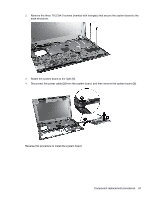
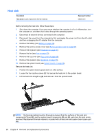
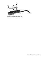
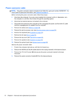
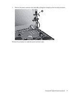
Power connector cable NOTE: The power connector cable is included in the Cable Kit, spare part number 650369-001. For more Cable Kit spare part information, see Cable Kit on page 23. Before removing the power connector cable, follow these steps: 1. Shut down the computer. If you are unsure whether the computer is off or in Hibernation, turn the computer on, and then shut it down through the operating system. 2. Disconnect all external devices connected to the computer. 3. Disconnect the power from the computer by first unplugging the power cord from the AC outlet and then unplugging the AC adapter from the computer. 4. Remove the battery (see Battery on page 36). 5. Remove the service access cover (see Service access cover on page 38). 6. Remove the keyboard (see Keyboard on page 50). 7. Remove the fan (see Fan on page 53). 8. Remove the top cover (see Top cover on page 55). 9. Remove the speakers (see Speakers on page 65). 10. Remove the system board (see System board on page 66). Remove the power connector cable: 1. Position the computer right-side up, with the front toward you. 2. Remove the WWAN and WLAN cables (1) from the routing channels in the base enclosure. 3. Remove the T8 2.5x3.0 screw (2) that secures the power connector bracket to the base enclosure. 4. Remove the power connector bracket (3) from the base enclosure. 70 Chapter 4 Removal and replacement procedures
-
 1
1 -
2
-
3
-
4
-
5
-
6
-
7
-
8
-
9
-
10
-
11
-
12
-
13
-
14
-
15
-
16
-
17
-
18
-
19
-
20
-
21
-
22
-
23
-
24
-
25
-
26
-
27
-
28
-
29
-
30
-
31
-
32
-
33
-
34
-
35
-
36
-
37
-
38
-
39
-
40
-
41
-
42
-
43
-
44
-
45
-
46
-
47
-
48
-
49
-
50
-
51
-
52
-
53
-
54
-
55
-
56
-
57
-
58
-
59
-
60
-
61
-
62
-
63
-
64
-
65
-
66
-
67
-
68
-
69
-
70
-
71
-
72
-
 73
73 -
 74
74 -
 75
75 -
 76
76 -
 77
77 -
 78
78 -
 79
79 -
 80
80 -
 81
81 -
 82
82 -
 83
83 -
84
-
85
-
86
-
87
-
88
-
89
-
90
-
91
-
92
-
93
-
94
-
95
-
96
-
97
-
98
-
99
-
100
-
101
-
102
-
103
-
104
-
105
-
106
-
107
-
108
-
109
-
110
-
111
-
112
-
113
-
114
-
115
-
116
-
117
-
118
-
119
-
120
-
121
-
122
-
123
-
124
-
125
-
126
-
127
-
128
-
129
 |
 |