HP ProBook 5330m HP ProBook 5330m Notebook PC - Maintenance and Service Guide - Page 83
Display assembly, Optional Remove the display panel see
 |
View all HP ProBook 5330m manuals
Add to My Manuals
Save this manual to your list of manuals |
Page 83 highlights
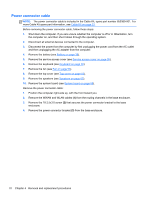
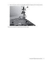
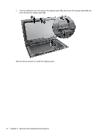
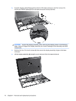
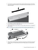
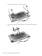
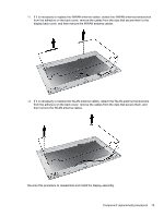
Display assembly Description Display bezel Webcam module Display Hinge Kit (includes left and right display hinges) Display hinge covers WLAN antennas and cables (included in the Antenna Kit, spare part number 650365-001) WWAN antennas and cables (included in the Antenna Kit, spare part number 650365-001) Display back cover Spare part number 650368-001 650405-001 650374-001 650376-001 650366-001 NOTE: Removing the display panel is not required to remove the display assembly. If it is necessary to remove the wecam module, WLAN module, or WWAN module, remove the display bezel for access to those components. For display bezel removal instructions, see Display panel on page 72. Before removing the display assembly, follow these steps: 1. Shut down the computer. If you are unsure whether the computer is off or in Hibernation, turn the computer on, and then shut it down through the operating system. 2. Disconnect all external devices connected to the computer. 3. Disconnect the power from the computer by first unplugging the power cord from the AC outlet and then unplugging the AC adapter from the computer. 4. Remove the battery (see Battery on page 36). 5. (Optional) Remove the display panel (see Display panel on page 72). 6. Remove the service access cover (see Service access cover on page 38). 7. Remove the keyboard (see Keyboard on page 50). 8. Remove the fan (see Fan on page 53). 9. Remove the top cover (see Top cover on page 55). 10. Remove the speakers (see Speakers on page 65). 11. Remove the system board (see System board on page 66). 12. Remove the power connector cable (see Power connector cable on page 70). Remove the display assembly: 1. Position the computer right-side up, with the front toward you. Component replacement procedures 75
-
 1
1 -
2
-
3
-
4
-
5
-
6
-
7
-
8
-
9
-
10
-
11
-
12
-
13
-
14
-
15
-
16
-
17
-
18
-
19
-
20
-
21
-
22
-
23
-
24
-
25
-
26
-
27
-
28
-
29
-
30
-
31
-
32
-
33
-
34
-
35
-
36
-
37
-
38
-
39
-
40
-
41
-
42
-
43
-
44
-
45
-
46
-
47
-
48
-
49
-
50
-
51
-
52
-
53
-
54
-
55
-
56
-
57
-
58
-
59
-
60
-
61
-
62
-
63
-
64
-
65
-
66
-
67
-
68
-
69
-
70
-
71
-
72
-
73
-
74
-
75
-
76
-
77
-
 78
78 -
 79
79 -
 80
80 -
 81
81 -
 82
82 -
 83
83 -
 84
84 -
 85
85 -
 86
86 -
 87
87 -
 88
88 -
89
-
90
-
91
-
92
-
93
-
94
-
95
-
96
-
97
-
98
-
99
-
100
-
101
-
102
-
103
-
104
-
105
-
106
-
107
-
108
-
109
-
110
-
111
-
112
-
113
-
114
-
115
-
116
-
117
-
118
-
119
-
120
-
121
-
122
-
123
-
124
-
125
-
126
-
127
-
128
-
129
 |
 |