HP ProBook 5330m HP ProBook 5330m Notebook PC - Maintenance and Service Guide - Page 84
CAUTION, Remove the four T8 2.5x4.0 screws
 |
View all HP ProBook 5330m manuals
Add to My Manuals
Save this manual to your list of manuals |
Page 84 highlights
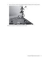
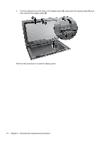
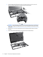
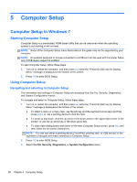
2. Feed the display cable (1) through the bottom of the base enclosure, and then remove the WLAN and WWAN cables (2) from the base enclosure routing channels. CAUTION: Support the display assembly when removing the display screws in the following steps. Failure to support the display assembly can result in damage to the assembly and other components. 3. Remove the four T8 2.5x4.0 screws (1) that secure the display assembly hinges to the base enclosure. 4. Lift the display assembly (2) straight up and remove it from the base enclosure. 76 Chapter 4 Removal and replacement procedures
-
 1
1 -
2
-
3
-
4
-
5
-
6
-
7
-
8
-
9
-
10
-
11
-
12
-
13
-
14
-
15
-
16
-
17
-
18
-
19
-
20
-
21
-
22
-
23
-
24
-
25
-
26
-
27
-
28
-
29
-
30
-
31
-
32
-
33
-
34
-
35
-
36
-
37
-
38
-
39
-
40
-
41
-
42
-
43
-
44
-
45
-
46
-
47
-
48
-
49
-
50
-
51
-
52
-
53
-
54
-
55
-
56
-
57
-
58
-
59
-
60
-
61
-
62
-
63
-
64
-
65
-
66
-
67
-
68
-
69
-
70
-
71
-
72
-
73
-
74
-
75
-
76
-
77
-
78
-
 79
79 -
 80
80 -
 81
81 -
 82
82 -
 83
83 -
 84
84 -
 85
85 -
 86
86 -
 87
87 -
 88
88 -
 89
89 -
90
-
91
-
92
-
93
-
94
-
95
-
96
-
97
-
98
-
99
-
100
-
101
-
102
-
103
-
104
-
105
-
106
-
107
-
108
-
109
-
110
-
111
-
112
-
113
-
114
-
115
-
116
-
117
-
118
-
119
-
120
-
121
-
122
-
123
-
124
-
125
-
126
-
127
-
128
-
129
 |
 |

2.
Feed the display cable
(1)
through the bottom of the base enclosure, and then remove the
WLAN and WWAN cables
(2)
from the base enclosure routing channels.
CAUTION:
Support the display assembly when removing the display screws in the following
steps. Failure to support the display assembly can result in damage to the assembly and other
components.
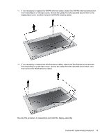
3.
Remove the four T8 2.5x4.0 screws
(1)
that secure the display assembly hinges to the base
enclosure.
4.
Lift the display assembly
(2)
straight up and remove it from the base enclosure.
76
Chapter 4
Removal and replacement procedures