HP ProBook 5330m HP ProBook 5330m Notebook PC - Maintenance and Service Guide - Page 85
Be careful not to scratch the silver paint when removing the display hinge covers., hinge cover
 |
View all HP ProBook 5330m manuals
Add to My Manuals
Save this manual to your list of manuals |
Page 85 highlights
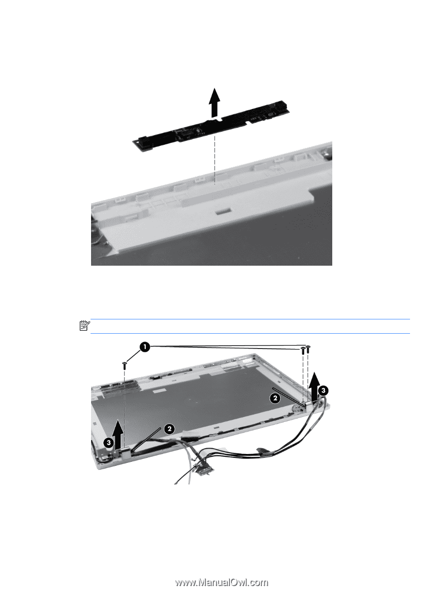
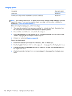
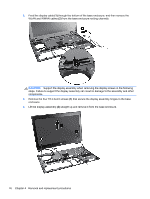
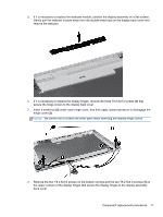
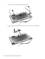
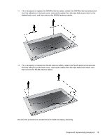
5. If it is necessary to replace the webcam module, position the display assembly on a flat surface. Gently pull the webcam module away from the double-sided tape on the display back cover and remove the webcam. 6. If it is necessary to replace the display hinges, remove the three T8 2.5x3.0 screws (1) that secure the hinge covers to the display back cover. 7. Insert a small tool (2) under each hinge cover, and then apply upward pressure to disengage the hinge cover (3). NOTE: Be careful not to scratch the silver paint when removing the display hinge covers. 8. Remove the four T8 2.5x4.0 screws on the bottom corners and the two T8 2.5x3.0 screws (1) on the upper corners of the display hinges that secure the display hinges to the display assembly back cover. Component replacement procedures 77
-
 1
1 -
2
-
3
-
4
-
5
-
6
-
7
-
8
-
9
-
10
-
11
-
12
-
13
-
14
-
15
-
16
-
17
-
18
-
19
-
20
-
21
-
22
-
23
-
24
-
25
-
26
-
27
-
28
-
29
-
30
-
31
-
32
-
33
-
34
-
35
-
36
-
37
-
38
-
39
-
40
-
41
-
42
-
43
-
44
-
45
-
46
-
47
-
48
-
49
-
50
-
51
-
52
-
53
-
54
-
55
-
56
-
57
-
58
-
59
-
60
-
61
-
62
-
63
-
64
-
65
-
66
-
67
-
68
-
69
-
70
-
71
-
72
-
73
-
74
-
75
-
76
-
77
-
78
-
79
-
 80
80 -
 81
81 -
 82
82 -
 83
83 -
 84
84 -
 85
85 -
 86
86 -
 87
87 -
 88
88 -
 89
89 -
 90
90 -
91
-
92
-
93
-
94
-
95
-
96
-
97
-
98
-
99
-
100
-
101
-
102
-
103
-
104
-
105
-
106
-
107
-
108
-
109
-
110
-
111
-
112
-
113
-
114
-
115
-
116
-
117
-
118
-
119
-
120
-
121
-
122
-
123
-
124
-
125
-
126
-
127
-
128
-
129
 |
 |