HP RP7 Hardware Reference Guide HP RP7 Retail System Model 7800
HP RP7 Manual
 |
View all HP RP7 manuals
Add to My Manuals
Save this manual to your list of manuals |
HP RP7 manual content summary:
- HP RP7 | Hardware Reference Guide HP RP7 Retail System Model 7800 - Page 1
Hardware Reference Guide HP RP7 Retail System Model 7800 - HP RP7 | Hardware Reference Guide HP RP7 Retail System Model 7800 - Page 2
Windows, and Windows Vista are either trademarks or registered trademarks of Microsoft Corporation in the United States and/or other countries. The only warranties for HP products and services . Hardware Reference Guide HP RP7 Retail System Model 7800 First Edition (May 2012) Document Part Number - HP RP7 | Hardware Reference Guide HP RP7 Retail System Model 7800 - Page 3
About This Book This guide provides basic information for upgrading this computer model. WARNING! Text set off in this manner indicates that failure to follow directions could result in bodily harm or loss of life. CAUTION: Text set - HP RP7 | Hardware Reference Guide HP RP7 Retail System Model 7800 - Page 4
iv About This Book - HP RP7 | Hardware Reference Guide HP RP7 Retail System Model 7800 - Page 5
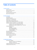
Installing the RP7 Adjustable Stand ...7 Routing Cables to External Devices 13 Installing Optional Integrated USB Modules 17 Installing an Optional HP Retail RP7 10.4" Customer Display 22 Installing an Optional HP Retail RP7 VFD Customer Display 28 Installing the VFD Customer Display Without - HP RP7 | Hardware Reference Guide HP RP7 Retail System Model 7800 - Page 6
Appendix A Troubleshooting ...65 Interpreting POST Diagnostic Front Panel LEDs and Audible Codes 65 Appendix B Electrostatic Discharge ...68 Preventing Electrostatic Damage ...68 Grounding Methods ...68 Appendix C Computer Operating - HP RP7 | Hardware Reference Guide HP RP7 Retail System Model 7800 - Page 7
: ◦ HP Retail Integrated Dual-Head MSR ◦ HP Retail Integrated Fingerprint Reader ◦ HP Retail Integrated Webcam ● Customer-facing two-line VFD (Vacuum Florescent Display); standard on select models (VFD can be mounted to the RP7 or mounted on a separate stand) ● Customer-facing 10.4" LCD Display - HP RP7 | Hardware Reference Guide HP RP7 Retail System Model 7800 - Page 8
choices ● DDR3 memory ● Operating system choices ● Integrated NIC and WiFi (some models) ● USB+PWR and cash drawer ports ● Hard drive and SSD choices ● RAID level 0,1 capable (RAID 1 can be HP factory preconfigured) ● Manageability tools ● Secure USB port (security screw provided) ● Energy Star - HP RP7 | Hardware Reference Guide HP RP7 Retail System Model 7800 - Page 9
1 HP RP7 Adjustable Stand 2 HP Retail RP7 VFD Customer Display 3 HP Retail RP7 10.4" Customer Display 4 HP Retail Integrated Webcam 5 HP Retail Integrated Fingerprint Reader 6 HP Retail Integrated Dual-Head MSR NOTE: A stand-alone VFD that is mounted on a separate stand is also available from HP ( - HP RP7 | Hardware Reference Guide HP RP7 Retail System Model 7800 - Page 10
or sleep mode. Using the On-Screen Display Menu Use the On-Screen Display (OSD) to adjust the screen image based on your viewing preferences. To access the OSD, do the following: 1. If the system is not already on, press the Power button to turn on the unit. 2. To activate the OSD function, tap in - HP RP7 | Hardware Reference Guide HP RP7 Retail System Model 7800 - Page 11
the contrast level of the screen. Color Selects and adjusts the screen color. OSD Control Adjusts the on-screen display (OSD) controls. Management Language Turns mode display and DDC/CI support on or off, and adjusts volume on models with integrated speakers. Selects the language in which the - HP RP7 | Hardware Reference Guide HP RP7 Retail System Model 7800 - Page 12
(for a secondary display or the 11 Parallel Port optional HP Retail RP7 10.4" Customer Display) 4 PS/2 Mouse/Keyboard Connector 12 RJ-45 Network Connector 5 DC Out Power Connector (for the optional HP 13 Serial Ports 5V/12V Retail RP7 10.4" Customer Display only) 6 USB Ports (6) 14 Powered USB - HP RP7 | Hardware Reference Guide HP RP7 Retail System Model 7800 - Page 13
safety information. This guide is located on the Web at http://www.hp.com/ergo. WARNING! RP7 Adjustable Stand NOTE: This section provides instructions for installing the RP7 Adjustable Stand if the stand was purchased separately. 1. Turn off the computer properly through the operating system - HP RP7 | Hardware Reference Guide HP RP7 Retail System Model 7800 - Page 14
3. Disconnect all cables from the rear I/O connectors. 4. Pull the power supply cover back then lift if up and off the unit. 5. Remove the decorative panel on the rear of the unit by gently prying the panel away from the base at the tab locations on the top and sides of the panel as - HP RP7 | Hardware Reference Guide HP RP7 Retail System Model 7800 - Page 15
mounting bracket by aligning the slots on the display head with the hooks on the mounting bracket and sliding the display down (1). Install the three screws included with the stand through the mounting bracket and into the display head to secure it in place (2). Installing the RP7 Adjustable Stand 9 - HP RP7 | Hardware Reference Guide HP RP7 Retail System Model 7800 - Page 16
8. Slide the mounting bracket cover down over the stand's mounting bracket. 9. Rotate open the small door at the base of the power supply housing (1) and slide the power supply brick into the housing (2). 10 Chapter 2 Hardware Upgrades - HP RP7 | Hardware Reference Guide HP RP7 Retail System Model 7800 - Page 17
the bottom of the stand's base, then through the cavity inside the base and connect the cord to the power supply brick. Insert the cord into the cable retainer clip on the side of the base and connect the other end of the cord to an electrical outlet. Installing the RP7 Adjustable Stand 11 - HP RP7 | Hardware Reference Guide HP RP7 Retail System Model 7800 - Page 18
12. Snap the decorative panel back onto the rear of the base. 13. Replace the power supply cover by lowering it down over the neck of the base then sliding it back until it snaps in place. 12 Chapter 2 Hardware Upgrades - HP RP7 | Hardware Reference Guide HP RP7 Retail System Model 7800 - Page 19
so that it snaps securely onto the chassis (2). 15. You can adjust the monitor stand height and tilt to a variety of positions. Choose a position that is the power-on state, voltage is always present on the system board as long as the system is plugged into an active AC outlet. You must disconnect - HP RP7 | Hardware Reference Guide HP RP7 Retail System Model 7800 - Page 20
3. Slide down the two levers on the upper corners of the rear I/O panel (1) and rotate the cover off (2). 4. Pull the power supply cover back then lift if up and off the unit. 14 Chapter 2 Hardware Upgrades - HP RP7 | Hardware Reference Guide HP RP7 Retail System Model 7800 - Page 21
5. Remove the decorative panel on the rear of the unit by gently prying the panel away from the base at the center of the base, then up through the cable retainer on the neck of the stand and into the appropriate I/O port. CAUTION: Be sure that the power cord is secured by the retainer clip next to - HP RP7 | Hardware Reference Guide HP RP7 Retail System Model 7800 - Page 22
7. Snap the decorative panel back onto the rear of the base. 8. Replace the power supply cover by lowering it down over the neck of the base then sliding it back until it snaps in place. 16 Chapter 2 Hardware Upgrades - HP RP7 | Hardware Reference Guide HP RP7 Retail System Model 7800 - Page 23
, do not install it on the sides of the display head. The webcam must be installed on top of the display head for proper video orientation. NOTE: These USB ports only support the USB modules listed above. They do not support optical drives or hard drives. Installing Optional Integrated USB Modules - HP RP7 | Hardware Reference Guide HP RP7 Retail System Model 7800 - Page 24
install a USB module: 1. Turn off the computer properly through the operating system, then turn off any external devices. 2. Disconnect the power cord from the power-on state, voltage is always present on the system board as long as the system is plugged into an active AC outlet. You must disconnect - HP RP7 | Hardware Reference Guide HP RP7 Retail System Model 7800 - Page 25
the display head (2). Remove only the cover plate that is in the location where you want to install the USB module. NOTE: There is a small "fingernail" slot in the center of the interior edge of the USB cover plate that can be used to help slide the cover plate off the unit - HP RP7 | Hardware Reference Guide HP RP7 Retail System Model 7800 - Page 26
6. Pull the plug that is inserted in the USB port out of the port. NOTE: Some models do not have plugs in the USB ports. 7. Slide the screw hole cover plate on the module back (1) and insert the USB connector on the module into the USB port (2). 20 Chapter 2 Hardware Upgrades - HP RP7 | Hardware Reference Guide HP RP7 Retail System Model 7800 - Page 27
8. Install the two screws that were previously removed (1) and slide the cover plate on the module forward to cover the screws (2). 9. Slide the display head's back panel down onto the rear of the display head. Installing Optional Integrated USB Modules 21 - HP RP7 | Hardware Reference Guide HP RP7 Retail System Model 7800 - Page 28
onto the chassis (2). 11. Reconnect the power cord and press the power button. Installing an Optional HP Retail RP7 10.4" Customer Display 1. Turn off the computer properly through the operating system, then turn off any external devices. 2. Disconnect the power cord from the power outlet. CAUTION - HP RP7 | Hardware Reference Guide HP RP7 Retail System Model 7800 - Page 29
3. Slide down the two levers on the upper corners of the rear I/O panel (1) and rotate the cover off (2). 4. Pull the power supply cover back then lift if up and off the unit. Installing an Optional HP Retail RP7 10.4" Customer Display 23 - HP RP7 | Hardware Reference Guide HP RP7 Retail System Model 7800 - Page 30
5. Remove the decorative panel on the rear of the unit by gently prying the panel away from the base at the tab locations on the to release the bottom tabs (3). 6. Connect the audio, DVI, USB, and power cables to the customer display. Insert the DVI cable into the retainer clip at the base of the - HP RP7 | Hardware Reference Guide HP RP7 Retail System Model 7800 - Page 31
aligned with the screw holes on the display. Install the two screws to secure the back plate to the display (3). 8. Slide the cable ends through the hole in the center of the decorative panel that was included with the customer display. Installing an Optional HP Retail RP7 10.4" Customer Display 25 - HP RP7 | Hardware Reference Guide HP RP7 Retail System Model 7800 - Page 32
cables through the rear of the base and out the front of the base, then up through the cable retainer on the neck of the RP7 stand and connect the cables to the RP7 I/O ports. 10. Snap the decorative panel onto the rear of the base. 26 Chapter 2 Hardware Upgrades - HP RP7 | Hardware Reference Guide HP RP7 Retail System Model 7800 - Page 33
the two screws included with the customer display into the screw holes on top of the mounting bracket (2). 12. Replace the power supply cover by lowering it down over the neck of the base then sliding it back until it snaps in place. Installing an Optional HP Retail RP7 10.4" Customer Display 27 - HP RP7 | Hardware Reference Guide HP RP7 Retail System Model 7800 - Page 34
it snaps securely onto the chassis (2). 14. Reconnect the power cord and press the power button on both displays. Installing an Optional HP Retail RP7 VFD Customer Display The integrated VFD customer display can be installed with no poles attached, or with one or two poles attached, depending on the - HP RP7 | Hardware Reference Guide HP RP7 Retail System Model 7800 - Page 35
3. Slide down the two levers on the upper corners of the rear I/O panel (1) and rotate the cover off (2). 4. Pull the power supply cover back then lift if up and off the unit. Installing an Optional HP Retail RP7 VFD Customer Display 29 - HP RP7 | Hardware Reference Guide HP RP7 Retail System Model 7800 - Page 36
panel on the rear of the unit by gently prying the panel away VFD through the rear of the base and out the front of the base (1), then though the cable retainer (2). Connect the extension cable to the I/O cable included with the VFD (3) and connect the I/O cable to the 12V USB port on the RP7 - HP RP7 | Hardware Reference Guide HP RP7 Retail System Model 7800 - Page 37
7. Wrap the excess extension cable around the hooks on the rear of the base. 8. Insert the end of the extension cable through the hole in the decorative panel (1) and snap the decorative panel onto the rear of the base (2). Installing an Optional HP Retail RP7 VFD Customer Display 31 - HP RP7 | Hardware Reference Guide HP RP7 Retail System Model 7800 - Page 38
9. Insert the VFD cable through the center of the mounting bracket (1) and slide the VFD onto the mounting bracket (2). 10. Lay the VFD face down on clean, dry cloth and connect the VFD cable to the extension cable. 32 Chapter 2 Hardware Upgrades - HP RP7 | Hardware Reference Guide HP RP7 Retail System Model 7800 - Page 39
(1), and install the two screws included with the VFD into the screw holes on top of the mounting bracket (2). 12. Replace the power supply cover by lowering it down over the neck of the base then sliding it back until it snaps in place. Installing an Optional HP Retail RP7 VFD Customer Display 33 - HP RP7 | Hardware Reference Guide HP RP7 Retail System Model 7800 - Page 40
onto the chassis (2). 14. Reconnect the power cord and press the power button. Installing the VFD Customer Display With One or Two Poles 1. Turn off the computer properly through the operating system, then turn off any external devices. 2. Disconnect the power cord from the power outlet. CAUTION - HP RP7 | Hardware Reference Guide HP RP7 Retail System Model 7800 - Page 41
Pull the power supply cover back then lift if up and off the unit. 5. Remove the decorative panel on the rear of the unit by gently prying the panel away from the base at the tab locations down on the panel to release the bottom tabs (3). Installing an Optional HP Retail RP7 VFD Customer Display 35 - HP RP7 | Hardware Reference Guide HP RP7 Retail System Model 7800 - Page 42
with the VFD, then through the rear of the base (1) and out the front of the base. Continue to route the extension cable up through the cable retainer (2) and connect the extension cable to the I/O cable included with the VFD (3). Connect the I/O cable to the 12V USB port on the RP7. 36 Chapter - HP RP7 | Hardware Reference Guide HP RP7 Retail System Model 7800 - Page 43
8. Wrap the excess extension cable around the hooks on the rear of the base. 9. Snap the decorative plate onto the rear of the base. Installing an Optional HP Retail RP7 VFD Customer Display 37 - HP RP7 | Hardware Reference Guide HP RP7 Retail System Model 7800 - Page 44
10. Slide the VFD mounting bracket into the mounting hole on the rear of the RP7 base (1), and install the two screws included with the VFD into the screw holes on top of the mounting bracket (2). 11. Replace the power supply cover by lowering it down over the neck of the - HP RP7 | Hardware Reference Guide HP RP7 Retail System Model 7800 - Page 45
of the I/O cover up so that it snaps securely onto the chassis (2). 13. Reconnect the power cord and press the power button. Installing an Optional HP Retail RP7 VFD Customer Display 39 - HP RP7 | Hardware Reference Guide HP RP7 Retail System Model 7800 - Page 46
inline memory modules (SODIMMs). SODIMMs The memory sockets on the system board can be populated with up to two industry-standard contain the mandatory Joint Electronic Device Engineering Council (JEDEC) specification In addition, the computer supports: ● 512-Mbit, 1-Gbit, 2-Gbit, 4-Gbit, and - HP RP7 | Hardware Reference Guide HP RP7 Retail System Model 7800 - Page 47
is equal to the memory capacity of the SODIMM in Channel B. ● The system will operate in flex mode if the memory capacity of the SODIMM in Channel the maximum operational speed is determined by the slowest SODIMM in the system. Installing SODIMMs CAUTION: You must disconnect the power cord and wait - HP RP7 | Hardware Reference Guide HP RP7 Retail System Model 7800 - Page 48
3. Slide down the two levers on the upper corners of the rear I/O panel (1) and rotate the cover off (2). 4. Press inward on the buttons located near the bottom sides of the display head's back panel (1) then slide the back panel up and off the display head (2). 42 Chapter 2 Hardware Upgrades - HP RP7 | Hardware Reference Guide HP RP7 Retail System Model 7800 - Page 49
5. Press down on the lever at the to of the memory access door (1) and rotate the door open (2). 6. To remove a SODIMM, press outward on the two latches on each side of the SODIMM (1) then pull the SODIMM out of the socket (2). Installing Additional Memory 43 - HP RP7 | Hardware Reference Guide HP RP7 Retail System Model 7800 - Page 50
7. To install a SODIMM, slide the new SODIMM into the socket at approximately a 30° angle (1) then press the SODIMM down into the socket (2) so that the latches lock it in place. NOTE: A memory module can be installed in only one way. Match the notch on the module with the tab on the memory socket. - HP RP7 | Hardware Reference Guide HP RP7 Retail System Model 7800 - Page 51
's back panel down onto the rear of the display head. 10. Replace the rear I/O cover by placing the hooks on the bottom of the cover into the slots on the bottom of the chassis (1). Then rotate - HP RP7 | Hardware Reference Guide HP RP7 Retail System Model 7800 - Page 52
transfer the data to the new drive. 1. Turn off the computer properly through the operating system, then turn off any external devices. 2. Disconnect the power cord from the power outlet. located near the bottom sides of the display head's back panel (1) then slide the back panel up and off the - HP RP7 | Hardware Reference Guide HP RP7 Retail System Model 7800 - Page 53
5. Open the hard drive door (1), then grasp the pull tab on the side of the hard drive and pull the hard drive out of the drive bay (2). 6. Remove the four screws from the sides of the hard drive carrier (1) and lift the hard drive out of the carrier (2). Removing and Installing a Hard Drive 47 - HP RP7 | Hardware Reference Guide HP RP7 Retail System Model 7800 - Page 54
7. Place the new hard drive into the carrier (1) and install the four screws into the sides of the carrier (2). 8. Slide the hard drive/carrier assembly into the drive bay (1) and close the hard drive door (2). 48 Chapter 2 Hardware Upgrades - HP RP7 | Hardware Reference Guide HP RP7 Retail System Model 7800 - Page 55
's back panel down onto the rear of the display head. 10. Replace the rear I/O cover by placing the hooks on the bottom of the cover into the slots on the bottom of the chassis (1). Then rotate - HP RP7 | Hardware Reference Guide HP RP7 Retail System Model 7800 - Page 56
with the HP spare customers to recycle used electronic hardware, HP original print cartridges, and rechargeable batteries. For more information about recycling programs, go to http://www.hp.com/ recycle. 1. Turn off the computer properly through the operating system system board as long as the system - HP RP7 | Hardware Reference Guide HP RP7 Retail System Model 7800 - Page 57
I/O panel (1) and rotate the cover off (2). 5. Disconnect all cables from the rear I/O connectors. 6. Press inward on the buttons located near the bottom sides of the display head's back panel (1) then slide the back panel up and off the - HP RP7 | Hardware Reference Guide HP RP7 Retail System Model 7800 - Page 58
7. Remove the RP7 display head from the stand by removing the three screws that attach the stand's mounting bracket to the display head (1) then slide the display up and off the mounting bracket (2). 8. Lay the display head face down on a surface covered by a clean, dry cloth. 9. Open the memory - HP RP7 | Hardware Reference Guide HP RP7 Retail System Model 7800 - Page 59
10. Remove the five screws that secure the metal plate on the back of the display head (1) and lift the metal plate off the display head (2). 11. Note which side of the battery is the positive side so that the new battery has the same orientation and pull the battery - HP RP7 | Hardware Reference Guide HP RP7 Retail System Model 7800 - Page 60
the new battery is oriented in the same direction as the battery that was removed. 13. Place the metal plate on the back of the display head (1) and secure it to the display head with the five screws that were previously removed (2). 54 Chapter 2 Hardware Upgrades - HP RP7 | Hardware Reference Guide HP RP7 Retail System Model 7800 - Page 61
power cable (3), and close the memory access door (4). 15. Attach the RP7 display head to the stand's mounting bracket by aligning the slots on the display head with the hooks on the mounting bracket and sliding the display down (1). Install the three screws through the mounting bracket and into the - HP RP7 | Hardware Reference Guide HP RP7 Retail System Model 7800 - Page 62
's back panel down onto the rear of the display head. 17. Reconnect all cables to the rear I/O connectors. 18. Replace the rear I/O cover by placing the hooks on the bottom of the cover into - HP RP7 | Hardware Reference Guide HP RP7 Retail System Model 7800 - Page 63
19. Slide the mounting bracket cover down over the stand's mounting bracket. 20. Plug in the power cord and press the power button. Using the USB Security Cover 1. Turn off the computer properly through the operating system, then turn off any external devices. 2. Disconnect the power cord from the - HP RP7 | Hardware Reference Guide HP RP7 Retail System Model 7800 - Page 64
4. Push inward on the tab at the bottom of the USB security cover (1) and rotate the bottom of the cover up (2) to remove it. 5. Insert the USB device into the USB port. 58 Chapter 2 Hardware Upgrades - HP RP7 | Hardware Reference Guide HP RP7 Retail System Model 7800 - Page 65
the USB device has a cable, place the cable in the channel on the side of the security cover. 7. If you want to secure the USB port, remove the security screw from the inside of the rear I/O panel and install the screw in the screw hole on the side of the USB - HP RP7 | Hardware Reference Guide HP RP7 Retail System Model 7800 - Page 66
the power button. Securing the RP7 to a Counter Top 1. Turn off the computer properly through the operating system, then turn off any external devices the power-on state, voltage is always present on the system board as long as the system is plugged into an active AC outlet. You must disconnect the - HP RP7 | Hardware Reference Guide HP RP7 Retail System Model 7800 - Page 67
screw holes on the base of the stand. Fasten the stand to the counter top using the appropriate fastening devices for your surface. NOTE: HP supplies wood screws for securing the base to be used to secure the RP7 rear panel and fix it to an external object. Installing an External Security Lock 61 - HP RP7 | Hardware Reference Guide HP RP7 Retail System Model 7800 - Page 68
Padlock A padlock can be used to secure the RP7 rear panel. 62 Chapter 2 Hardware Upgrades - HP RP7 | Hardware Reference Guide HP RP7 Retail System Model 7800 - Page 69
MSR and VFD Customer Display To configure the MSR and VFD, refer to the HP Point of Sale Configuration Guide (available in English only). The guide is available on the system's hard drive. In Windows XP or Windows Embedded POSReady 2009, select Start > All Programs > HP Point of Sale Information to - HP RP7 | Hardware Reference Guide HP RP7 Retail System Model 7800 - Page 70
for each individual serial port: ● Standard ● 5v on pins 1 and 9 ● 12v on pins 1 and 9 NOTE: To access the Computer F10 Setup utility, restart the computer and press the F10 key as soon as the HP logo screen is displayed (before the computer boots to the operating system). 64 Chapter 3 Configuring - HP RP7 | Hardware Reference Guide HP RP7 Retail System Model 7800 - Page 71
Troubleshooting from the wall outlet and allow the internal system components to cool before touching. NOTE: If until problem is solved. Computer on. None Computer in Suspend to RAM mode (some models only) assembly. Contact an authorized reseller or service provider. Processor not installed (not - HP RP7 | Hardware Reference Guide HP RP7 Retail System Model 7800 - Page 72
isolate the faulty module. 3. Replace third-party memory with HP memory. 4. Replace the system board. Red Power LED flashes six 6 times, once every until problem is solved. Invalid ROM based on bad checksum. 1. Reflash the system ROM with the latest BIOS image. 2. Replace the system board. - HP RP7 | Hardware Reference Guide HP RP7 Retail System Model 7800 - Page 73
hard drive LED turns green, the power button is working correctly. Replace the system board. OR Press and hold the power button for less than 4 seconds. If the hard drive LED does not turn on green then: 1. Check that the unit is plugged into a working AC outlet. 2. Ensure that the DC power cable - HP RP7 | Hardware Reference Guide HP RP7 Retail System Model 7800 - Page 74
standing on conductive floors or dissipating floor mats. ● Use conductive field service tools. ● Use a portable field service kit with a folding static-dissipating work mat. If you do not have any of the suggested equipment for proper grounding, contact an HP authorized dealer, reseller, or service - HP RP7 | Hardware Reference Guide HP RP7 Retail System Model 7800 - Page 75
material. ● Install or enable power management functions of the operating system or other software, including sleep states. ● Turn off the computer Screen Maintenance Keep your display and touch sensor clean. The touch sensor requires very little maintenance. HP recommends that you periodically - HP RP7 | Hardware Reference Guide HP RP7 Retail System Model 7800 - Page 76
the backup media is not exposed to electrical or magnetic impulses while stored or in transit. NOTE: The hard drive locks automatically when the system power is turned off. 2. Remove and store all removable media. 3. Turn off the computer and external devices. 4. Disconnect the power cord from the - HP RP7 | Hardware Reference Guide HP RP7 Retail System Model 7800 - Page 77
69 counter top, securing 60 customer display, installing 22 E electrostatic discharge, preventing damage 68 S security locks 61 serial ports, configuring for power 64 shipping preparation 70 stand, installing 7 T touch screen calibration 63 maintenance 69 troubleshooting 65 U USB security cover 57
-
 1
1 -
 2
2 -
 3
3 -
 4
4 -
 5
5 -
 6
6 -
 7
7 -
8
-
9
-
10
-
11
-
12
-
13
-
14
-
15
-
16
-
17
-
18
-
19
-
20
-
21
-
22
-
23
-
24
-
25
-
26
-
27
-
28
-
29
-
30
-
31
-
32
-
33
-
34
-
35
-
36
-
37
-
38
-
39
-
40
-
41
-
42
-
43
-
44
-
45
-
46
-
47
-
48
-
49
-
50
-
51
-
52
-
53
-
54
-
55
-
56
-
57
-
58
-
59
-
60
-
61
-
62
-
63
-
64
-
65
-
66
-
67
-
68
-
69
-
70
-
71
-
72
-
73
-
74
-
75
-
76
-
77
 |
 |

Hardware Reference Guide
HP RP7 Retail System Model 7800