HP RP7 Hardware Reference Guide HP RP7 Retail System Model 7800 - Page 31
Slide the cable ends through the hole in the center of the decorative panel that was included
 |
View all HP RP7 manuals
Add to My Manuals
Save this manual to your list of manuals |
Page 31 highlights
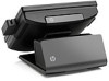
7. Route the audio, DVI, USB, and power cables through the hole in the customer display back plate (1). Connect the back plate to the customer display by aligning the hooks on the back plate with the slots on the back of the display and sliding the back plate up (2) so that the screw holes on the back plate are aligned with the screw holes on the display. Install the two screws to secure the back plate to the display (3). 8. Slide the cable ends through the hole in the center of the decorative panel that was included with the customer display. Installing an Optional HP Retail RP7 10.4" Customer Display 25
-
 1
1 -
2
-
3
-
4
-
5
-
6
-
7
-
8
-
9
-
10
-
11
-
12
-
13
-
14
-
15
-
16
-
17
-
18
-
19
-
20
-
21
-
22
-
23
-
24
-
25
-
 26
26 -
 27
27 -
 28
28 -
 29
29 -
 30
30 -
 31
31 -
 32
32 -
 33
33 -
 34
34 -
 35
35 -
 36
36 -
37
-
38
-
39
-
40
-
41
-
42
-
43
-
44
-
45
-
46
-
47
-
48
-
49
-
50
-
51
-
52
-
53
-
54
-
55
-
56
-
57
-
58
-
59
-
60
-
61
-
62
-
63
-
64
-
65
-
66
-
67
-
68
-
69
-
70
-
71
-
72
-
73
-
74
-
75
-
76
-
77
 |
 |

7.
Route the audio, DVI, USB, and power cables through the hole in the customer display back
plate (1). Connect the back plate to the customer display by aligning the hooks on the back plate
with the slots on the back of the display and sliding the back plate up (2) so that the screw holes
on the back plate are aligned with the screw holes on the display. Install the two screws to
secure the back plate to the display (3).
8.
Slide the cable ends through the hole in the center of the decorative panel that was included with
the customer display.
Installing an Optional HP Retail RP7 10.4” Customer Display
25