HP TouchSmart tm2-1020tx HP TouchSmart tm2 Notebook PC - Maintenance and Servi - Page 69
Power switch board, Release the ZIF connector to which the power switch board cable is connected
 |
View all HP TouchSmart tm2-1020tx manuals
Add to My Manuals
Save this manual to your list of manuals |
Page 69 highlights
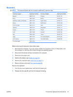
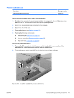
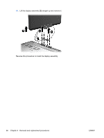
Power switch board Description Power switch board (includes cable) Spare part number 592968-001 Before removing the power switch board, follow these steps: 1. Shut down the computer. If you are unsure whether the computer is off or in Hibernation, turn the computer on, and then shut it down through the operating system. 2. Disconnect all external devices connected to the computer. 3. Disconnect the power cord. 4. Remove the battery (see Battery on page 39). 5. Remove the following components: a. Hard drive (see Hard drive on page 41). b. Memory cover (see Memory module on page 47). c. Top cover (see Top cover on page 55). Remove the power switch board: 1. Release the ZIF connector to which the power switch board cable is connected, and then disconnect the power switch board cable (1) from the system board. 2. Remove the power switch board (2) from the slot built into the base enclosure. Reverse this procedure to install the power switch board. ENWW Component replacement procedures 61
-
 1
1 -
2
-
3
-
4
-
5
-
6
-
7
-
8
-
9
-
10
-
11
-
12
-
13
-
14
-
15
-
16
-
17
-
18
-
19
-
20
-
21
-
22
-
23
-
24
-
25
-
26
-
27
-
28
-
29
-
30
-
31
-
32
-
33
-
34
-
35
-
36
-
37
-
38
-
39
-
40
-
41
-
42
-
43
-
44
-
45
-
46
-
47
-
48
-
49
-
50
-
51
-
52
-
53
-
54
-
55
-
56
-
57
-
58
-
59
-
60
-
61
-
62
-
63
-
 64
64 -
 65
65 -
 66
66 -
 67
67 -
 68
68 -
 69
69 -
 70
70 -
 71
71 -
 72
72 -
 73
73 -
 74
74 -
75
-
76
-
77
-
78
-
79
-
80
-
81
-
82
-
83
-
84
-
85
-
86
-
87
-
88
-
89
-
90
-
91
-
92
-
93
-
94
-
95
-
96
-
97
-
98
-
99
-
100
-
101
-
102
-
103
-
104
-
105
-
106
-
107
-
108
-
109
-
110
-
111
-
112
-
113
-
114
-
115
-
116
-
117
-
118
-
119
-
120
-
121
-
122
-
123
-
124
 |
 |