HP TouchSmart tm2-1020tx HP TouchSmart tm2 Notebook PC - Maintenance and Servi - Page 77
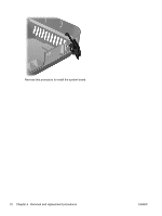
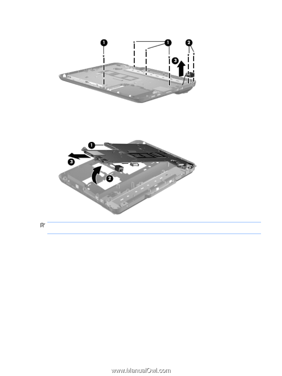
by sliding it up and to the right., After removing the system board
 |
View all HP TouchSmart tm2-1020tx manuals
Add to My Manuals
Save this manual to your list of manuals |
Page 77 highlights
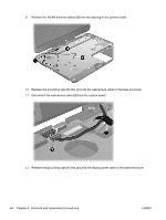
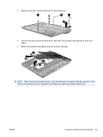
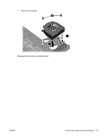
5. Release the power connector (3) from the base enclosure. 6. Use the hard drive connector (1) to lift the right side of the system board (2) until it rests at an angle. 7. Remove the system board (3) by sliding it up and to the right. NOTE: After removing the system board, it may be necessary to replace the RJ-45 connector cover. The RJ-45 connector cover is included in the Plastics Kit, spare part number 592971-001. ENWW Component replacement procedures 69
-
 1
1 -
2
-
3
-
4
-
5
-
6
-
7
-
8
-
9
-
10
-
11
-
12
-
13
-
14
-
15
-
16
-
17
-
18
-
19
-
20
-
21
-
22
-
23
-
24
-
25
-
26
-
27
-
28
-
29
-
30
-
31
-
32
-
33
-
34
-
35
-
36
-
37
-
38
-
39
-
40
-
41
-
42
-
43
-
44
-
45
-
46
-
47
-
48
-
49
-
50
-
51
-
52
-
53
-
54
-
55
-
56
-
57
-
58
-
59
-
60
-
61
-
62
-
63
-
64
-
65
-
66
-
67
-
68
-
69
-
70
-
71
-
 72
72 -
 73
73 -
 74
74 -
 75
75 -
 76
76 -
 77
77 -
 78
78 -
 79
79 -
 80
80 -
 81
81 -
 82
82 -
83
-
84
-
85
-
86
-
87
-
88
-
89
-
90
-
91
-
92
-
93
-
94
-
95
-
96
-
97
-
98
-
99
-
100
-
101
-
102
-
103
-
104
-
105
-
106
-
107
-
108
-
109
-
110
-
111
-
112
-
113
-
114
-
115
-
116
-
117
-
118
-
119
-
120
-
121
-
122
-
123
-
124
 |
 |
5.
Release the power connector
(3)
from the base enclosure.
6.
Use the hard drive connector
(1)
to lift the right side of the system board
(2)
until it rests at an
angle.
7.
Remove the system board
(3)
by sliding it up and to the right.
NOTE:
After removing the system board, it may be necessary to replace the RJ-45 connector cover.
The RJ-45 connector cover is included in the Plastics Kit, spare part number 592971-001.
ENWW
Component replacement procedures
69