HP TouchSmart tm2-1020tx HP TouchSmart tm2 Notebook PC - Maintenance and Servi - Page 73
CAUTION, support the display assembly can result in damage to the display assembly and other computer
 |
View all HP TouchSmart tm2-1020tx manuals
Add to My Manuals
Save this manual to your list of manuals |
Page 73 highlights
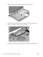
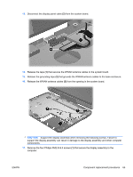
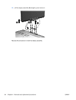
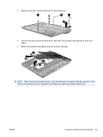
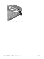
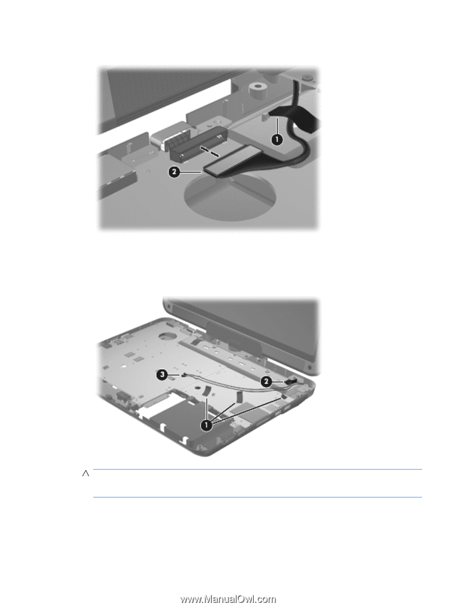
13. Disconnect the display panel cable (2) from the system board. 14. Release the tape (1) that secures the WWAN antenna cables to the system board. 15. Release the grounding tape (2) that grounds the WWAN antenna cables to the base enclosure. 16. Release the WWAN antenna cables (3) from the opening in the system board. CAUTION: Support the display assembly when removing the following screws. Failure to support the display assembly can result in damage to the display assembly and other computer components. 17. Remove the four Phillips PM2.5×6.0 screws (1) that secure the display assembly to the computer. ENWW Component replacement procedures 65
-
 1
1 -
2
-
3
-
4
-
5
-
6
-
7
-
8
-
9
-
10
-
11
-
12
-
13
-
14
-
15
-
16
-
17
-
18
-
19
-
20
-
21
-
22
-
23
-
24
-
25
-
26
-
27
-
28
-
29
-
30
-
31
-
32
-
33
-
34
-
35
-
36
-
37
-
38
-
39
-
40
-
41
-
42
-
43
-
44
-
45
-
46
-
47
-
48
-
49
-
50
-
51
-
52
-
53
-
54
-
55
-
56
-
57
-
58
-
59
-
60
-
61
-
62
-
63
-
64
-
65
-
66
-
67
-
 68
68 -
 69
69 -
 70
70 -
 71
71 -
 72
72 -
 73
73 -
 74
74 -
 75
75 -
 76
76 -
 77
77 -
 78
78 -
79
-
80
-
81
-
82
-
83
-
84
-
85
-
86
-
87
-
88
-
89
-
90
-
91
-
92
-
93
-
94
-
95
-
96
-
97
-
98
-
99
-
100
-
101
-
102
-
103
-
104
-
105
-
106
-
107
-
108
-
109
-
110
-
111
-
112
-
113
-
114
-
115
-
116
-
117
-
118
-
119
-
120
-
121
-
122
-
123
-
124
 |
 |
13.
Disconnect the display panel cable
(2)
from the system board.
14.
Release the tape
(1)
that secures the WWAN antenna cables to the system board.
15.
Release the grounding tape
(2)
that grounds the WWAN antenna cables to the base enclosure.
16.
Release the WWAN antenna cables
(3)
from the opening in the system board.
CAUTION:
Support the display assembly when removing the following screws. Failure to
support the display assembly can result in damage to the display assembly and other computer
components.
17.
Remove the four Phillips PM2.5×6.0 screws
(1)
that secure the display assembly to the
computer.
ENWW
Component replacement procedures
65