HP TouchSmart tm2-1020tx HP TouchSmart tm2 Notebook PC - Maintenance and Servi - Page 82
Heat sink, Steps 2 and 3 apply only to computer models equipped with a discrete graphics
 |
View all HP TouchSmart tm2-1020tx manuals
Add to My Manuals
Save this manual to your list of manuals |
Page 82 highlights
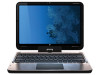
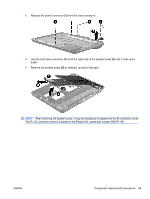
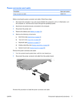
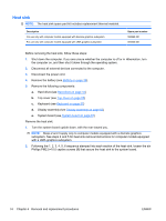
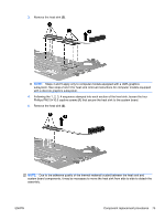
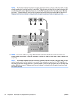
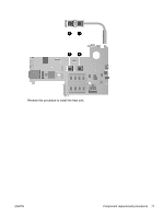
Heat sink NOTE: The heat sink spare part kit includes replacement thermal material. Description For use only with computer models equipped with discrete graphics subsystem For use only with computer models equipped with UMA graphics subsystem Spare part number 592969-001 594635-001 Before removing the heat sink, follow these steps: 1. Shut down the computer. If you are unsure whether the computer is off or in Hibernation, turn the computer on, and then shut it down through the operating system. 2. Disconnect all external devices connected to the computer. 3. Disconnect the power cord. 4. Remove the battery (see Battery on page 39). 5. Remove the following components: a. Hard drive (see Hard drive on page 41) b. Top cover (see Top cover on page 55) c. Keyboard (see Keyboard on page 57) d. Display assembly (see Display assembly on page 62) e. System board (see System board on page 67) Remove the heat sink: 1. Turn the system board upside down, with the rear toward you. NOTE: Steps 2 and 3 apply only to computer models equipped with a discrete graphics subsystem. See steps 4 and 5 for heat sink removal instructions for computer models equipped with a UMA graphics subsystem. 2. Following the 1, 2, 3, 4, 5, 6 sequence stamped into each section of the heat sink, loosen the six Phillips PM2.5×10.0 captive screws (1) that secure the heat sink to the system board. 74 Chapter 4 Removal and replacement procedures ENWW
-
 1
1 -
2
-
3
-
4
-
5
-
6
-
7
-
8
-
9
-
10
-
11
-
12
-
13
-
14
-
15
-
16
-
17
-
18
-
19
-
20
-
21
-
22
-
23
-
24
-
25
-
26
-
27
-
28
-
29
-
30
-
31
-
32
-
33
-
34
-
35
-
36
-
37
-
38
-
39
-
40
-
41
-
42
-
43
-
44
-
45
-
46
-
47
-
48
-
49
-
50
-
51
-
52
-
53
-
54
-
55
-
56
-
57
-
58
-
59
-
60
-
61
-
62
-
63
-
64
-
65
-
66
-
67
-
68
-
69
-
70
-
71
-
72
-
73
-
74
-
75
-
76
-
 77
77 -
 78
78 -
 79
79 -
 80
80 -
 81
81 -
 82
82 -
 83
83 -
 84
84 -
 85
85 -
 86
86 -
 87
87 -
88
-
89
-
90
-
91
-
92
-
93
-
94
-
95
-
96
-
97
-
98
-
99
-
100
-
101
-
102
-
103
-
104
-
105
-
106
-
107
-
108
-
109
-
110
-
111
-
112
-
113
-
114
-
115
-
116
-
117
-
118
-
119
-
120
-
121
-
122
-
123
-
124
 |
 |