HP TouchSmart tm2-1020tx HP TouchSmart tm2 Notebook PC - Maintenance and Servi - Page 76
USB/Card Reader board see
 |
View all HP TouchSmart tm2-1020tx manuals
Add to My Manuals
Save this manual to your list of manuals |
Page 76 highlights
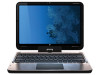
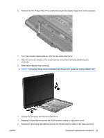
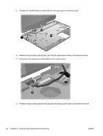
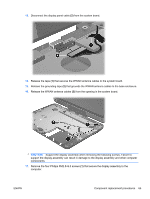
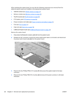
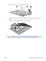
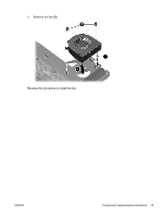
When replacing the system board, be sure that the following components are removed from the defective system board and installed on the replacement system board: ● WWAN module (see WWAN module on page 44) ● Memory module (see Memory module on page 47) ● WLAN module (see WLAN module on page 50) ● RTC battery (see RTC battery on page 54) ● Power connector and cable (see Power connector and cable on page 71) ● Fan (see Fan on page 72) ● Heat sink (see Heat sink on page 74) ● USB/Card Reader board (see USB/Card Reader board on page 78) Remove the system board: 1. Disconnect the Bluetooth module cable (1) from the system board. 2. Release the ZIF connector to which the power switch board cable is connected, and disconnect the power switch board cable (2) from the system board. 3. Remove the four Phillips PM2.5×4.0 screws (1) that secure the system board to the base enclosure. 4. Remove the two Phillips PM2.5×4.0 screws (2) that secure the power connector to the base enclosure. 68 Chapter 4 Removal and replacement procedures ENWW
-
 1
1 -
2
-
3
-
4
-
5
-
6
-
7
-
8
-
9
-
10
-
11
-
12
-
13
-
14
-
15
-
16
-
17
-
18
-
19
-
20
-
21
-
22
-
23
-
24
-
25
-
26
-
27
-
28
-
29
-
30
-
31
-
32
-
33
-
34
-
35
-
36
-
37
-
38
-
39
-
40
-
41
-
42
-
43
-
44
-
45
-
46
-
47
-
48
-
49
-
50
-
51
-
52
-
53
-
54
-
55
-
56
-
57
-
58
-
59
-
60
-
61
-
62
-
63
-
64
-
65
-
66
-
67
-
68
-
69
-
70
-
 71
71 -
 72
72 -
 73
73 -
 74
74 -
 75
75 -
 76
76 -
 77
77 -
 78
78 -
 79
79 -
 80
80 -
 81
81 -
82
-
83
-
84
-
85
-
86
-
87
-
88
-
89
-
90
-
91
-
92
-
93
-
94
-
95
-
96
-
97
-
98
-
99
-
100
-
101
-
102
-
103
-
104
-
105
-
106
-
107
-
108
-
109
-
110
-
111
-
112
-
113
-
114
-
115
-
116
-
117
-
118
-
119
-
120
-
121
-
122
-
123
-
124
 |
 |