IBM 8837 User Guide - Page 23
Remind, button, Reset, Light, diagnostic - specs
 |
UPC - 000435421401
View all IBM 8837 manuals
Add to My Manuals
Save this manual to your list of manuals |
Page 23 highlights
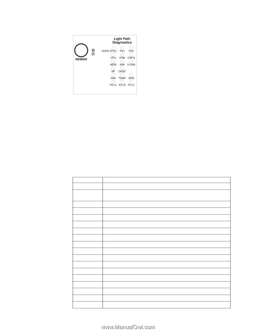
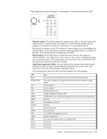
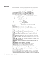
Path Diagnostics panel, followed by a description of the buttons and each LED. v Remind button: This button places the system-error LED on the front panel into remind mode. In remind mode, the system error LED flashes rapidly until the problem is corrected, the system is restarted, or a new problem occurs. By placing the system error LED indicator in remind mode, you acknowledge that you are aware of the last failure but will not take immediate action to correct the problem. The remind function is handled by the BMC. v Reset button: Press this button to reset the server and run the power-on self-test (POST). You might have to use a pen or the end of a straightened paper clip to press the button. The reset button is to the right of the remind button and just above the small circle with the R inside. v Light Path diagnostic LEDs: You can slide out the operator information panel and drop it down for easy viewing without opening the top server cover. The LEDs are on the top of the operator information panel. The following table lists the LEDs and the problems that they indicate. LED None OVER SPEC PS1 PS2 CPU VRM CNFG MEM NMI S ERR SP DASD FAN TEMP BRD PCI-A PCI-B PCI-C Error An error that is not reflected in the Light Path diagnostics panel The power supplies are using more power than their maximum rating allows Power supply 1 Power supply 2 Microprocessor error Voltage Regulator Module (VRM) Configuration error, check the microprocessor and memory configuration Memory Nonmaskable interrupt Soft error Service processor Hard disk drive Fan (TEMP LED might also be lit) System temperature Error with the system board, or a battery fault PCI-A bus PCI-B bus PCI-C bus Chapter 1. Introducing the xSeries 336 Type 8837 server 11
-
 1
1 -
2
-
3
-
4
-
5
-
6
-
7
-
8
-
9
-
10
-
11
-
12
-
13
-
14
-
15
-
16
-
17
-
 18
18 -
 19
19 -
 20
20 -
 21
21 -
 22
22 -
 23
23 -
 24
24 -
 25
25 -
 26
26 -
 27
27 -
 28
28 -
29
-
30
-
31
-
32
-
33
-
34
-
35
-
36
-
37
-
38
-
39
-
40
-
41
-
42
-
43
-
44
-
45
-
46
-
47
-
48
-
49
-
50
-
51
-
52
-
53
-
54
-
55
-
56
-
57
-
58
-
59
-
60
-
61
-
62
-
63
-
64
-
65
-
66
-
67
-
68
-
69
-
70
 |
 |