IBM 8837 User Guide - Page 24
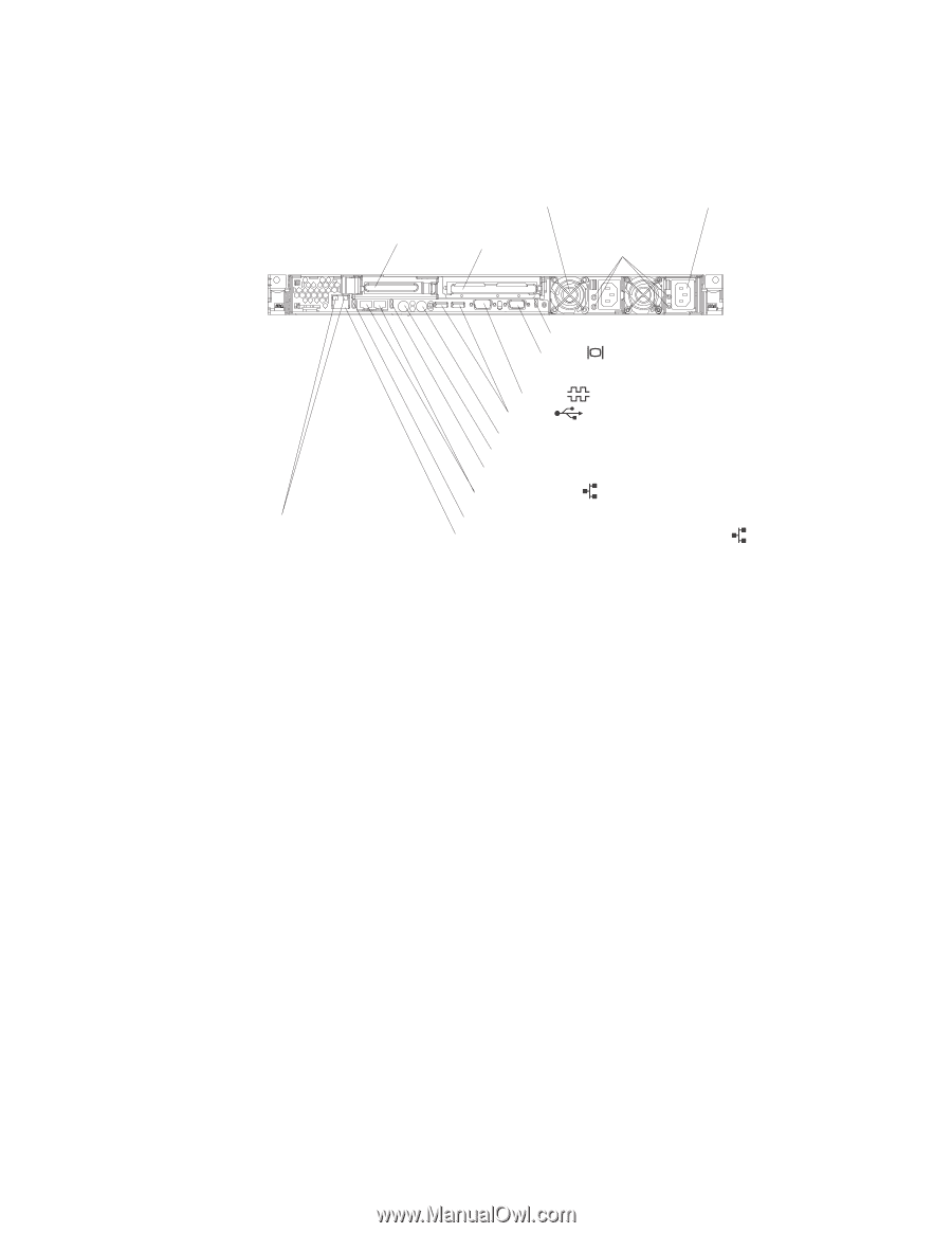
Power, supply, Location, System-error, Video, connector, Serial, connectors, Keyboard, Mouse,
 |
UPC - 000435421401
View all IBM 8837 manuals
Add to My Manuals
Save this manual to your list of manuals |
Page 24 highlights
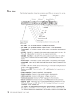
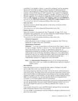
Rear view The following illustration shows the connectors and LEDs on the rear of the server. Power supply 2 Power supply 1 PCI slot 1 PCI slot 2 AC and DC LEDs 3 rear LEDs (Power, Location, System-error) Video Serial USBs Keyboard Mouse Ethernet LEDs Dual GB Ethernet Remote Supervisor Adapter II SlimLine Ethernet LEDs Ethernet LEDs Remote Supervisor Adapter II SlimLine Ethernet v PCI slot 1: This slot allows insertion of a low profile adapter. v PCI slot 2: This slot allows insertion of any PCI-X or PCI-E type adapter. v Power supply 2: Provides dc power to the server, is a redundant backup power supply. v AC LED: This LED is to the left of the power-cord connector and is the top LED. This LED indicates that the server has an ac power connection. v DC LED: This LED is to the left of the power-cord connector and is the bottom LED. This LED indicates that the power supply is providing dc power to the server. v Power supply 1: Provides dc power to the server, is the primary power supply. v Power LED: This is the top LED and it indicates that ac power is present on the server. v Location LED: This middle (blue) LED assists you in visually locating the server when it is among other servers v System-error LED: This is the bottom LED and it indicates that a system error occurred. v Video connector: Connect a monitor to this connector. v Serial connector: Connect a 9-pin serial device to this connector. v USB connectors: Connect a USB device to these connectors. v Keyboard connector: Connect a PS/2® keyboard to this connector. v Mouse connector: Connect a mouse or other PS/2 device to this connector. v Ethernet LEDs: There are a set of LEDs for each Ethernet connector. The top LED is the Ethernet link LED. When it is lit, it indicates that there is an active connection on the Ethernet port. The bottom LED is the Ethernet activity LED. When it flashes, it indicates that data is being transmitted or received between the server and a network device. The flashing frequency is proportional to the amount of traffic on the network link. 12 IBM xSeries 336 Type 8837: User's Guide
-
 1
1 -
2
-
3
-
4
-
5
-
6
-
7
-
8
-
9
-
10
-
11
-
12
-
13
-
14
-
15
-
16
-
17
-
18
-
 19
19 -
 20
20 -
 21
21 -
 22
22 -
 23
23 -
 24
24 -
 25
25 -
 26
26 -
 27
27 -
 28
28 -
 29
29 -
30
-
31
-
32
-
33
-
34
-
35
-
36
-
37
-
38
-
39
-
40
-
41
-
42
-
43
-
44
-
45
-
46
-
47
-
48
-
49
-
50
-
51
-
52
-
53
-
54
-
55
-
56
-
57
-
58
-
59
-
60
-
61
-
62
-
63
-
64
-
65
-
66
-
67
-
68
-
69
-
70
 |
 |