IBM 8862 User Manual - Page 30
xSeries, Installation, Guide
 |
UPC - 000435172679
View all IBM 8862 manuals
Add to My Manuals
Save this manual to your list of manuals |
Page 30 highlights
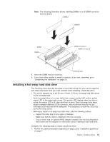
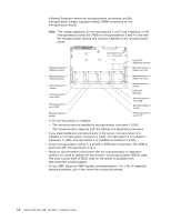
following illustration shows the microprocessor connectors and the microprocessor voltage regulator module (VRM) connectors on the microprocessor board. Note: The voltage regulators for microprocessors 1 and 2 are integrated on the microprocessor board; the VRMs for microprocessors 3 and 4 come with the microprocessor options and must be installed on the microprocessor board. Microprocessor 3 VRM error LED Light-path diagnostics button Microprocessor 4 VRM error LED Microprocessor 3 VRM connector Microprocessor 4 VRM connector Microprocessor 1 socket Microprocessor 1 error LED Microprocessor 2 error LED Microprocessor 4 socket Light-path test LED Microprocessor 4 error LED Microprocessor 3 socket Microprocessor 2 socket Microprocessor 3 error LED v If one microprocessor is installed: - The microprocessor is installed in microprocessor connector 1 (U22). - The microprocessor supports both the startup and application processes. v If you install additional microprocessors in the server, microprocessor 2 is installed in microprocessor connector 2 (U23); microprocessor 3 is installed in connector 3 (U24); microprocessor 4 is installed in connector 4 (U25). v A new microprocessor comes in a kit with a VRM and a heat sink. The VRM is used only with microprocessor 3 or 4. v Read the documentation that comes with the microprocessor to determine whether you need to update the server basic input/output system (BIOS) code. The most current level of BIOS code for the server is available from http://www.ibm.com/pc/support. v To use SMP, obtain an SMP-capable operating system. For a list of supported operating systems, go to http://www.ibm.com/pc/us/compat/. 18 xSeries 365 Type 8861 and 8862: Installation Guide
-
 1
1 -
2
-
3
-
4
-
5
-
6
-
7
-
8
-
9
-
10
-
11
-
12
-
13
-
14
-
15
-
16
-
17
-
18
-
19
-
20
-
21
-
22
-
23
-
24
-
 25
25 -
 26
26 -
 27
27 -
 28
28 -
 29
29 -
 30
30 -
 31
31 -
 32
32 -
 33
33 -
 34
34 -
 35
35 -
36
-
37
-
38
-
39
-
40
-
41
-
42
-
43
-
44
-
45
-
46
-
47
-
48
-
49
-
50
-
51
-
52
-
53
-
54
-
55
-
56
-
57
-
58
-
59
-
60
-
61
-
62
-
63
-
64
-
65
-
66
-
67
-
68
-
69
-
70
-
71
-
72
-
73
-
74
-
75
-
76
-
77
-
78
-
79
-
80
-
81
-
82
-
83
-
84
-
85
-
86
-
87
-
88
-
89
-
90
-
91
-
92
-
93
-
94
-
95
-
96
-
97
-
98
-
99
-
100
-
101
-
102
-
103
-
104
 |
 |
