Intel E7500 Design Guide
Intel E7500 Manual
 |
View all Intel E7500 manuals
Add to My Manuals
Save this manual to your list of manuals |
Intel E7500 manual content summary:
- Intel E7500 | Design Guide - Page 1
R Intel® E7500 Chipset Design Guide E7500 Memory Controller Hub (MCH) Thermal and Mechanical Design Guidelines February 2002 Document Number: 298647-001 - Intel E7500 | Design Guide - Page 2
future changes to them. The Intel® E7500 chipset MCH may contain design defects or errors known as errata which may cause the product to deviate from published specifications. Current characterized errata are available on request. Contact your local Intel sales office or your distributor to obtain - Intel E7500 | Design Guide - Page 3
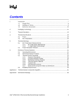
Documents 10 2 Packaging Technology ...11 3 Thermal Simulation...13 4 Thermal Specifications ...15 4.1 Power ...15 4.2 Die Temperature 15 5 Thermal Metrology Solution Component Suppliers 31 Appendix B: Mechanical Drawings...33 Intel® E7500 MCH Thermal and Mechanical Design Guidelines 3 - Intel E7500 | Design Guide - Page 4
28 Figure 17. Retention Mechanism Component Keep-out Zones 29 Figure 18. Intel® MCH Heatsink Assembly 34 Figure 19. Intel® MCH Heatsink Clip 35 Tables Table 1. Intel® E7500 MCH Thermal Specifications 15 Table 2. Reliability Requirements 30 Table 3. Complete Thermal Solution Kits 31 Table - Intel E7500 | Design Guide - Page 5
R Revision History Revision Number -001 Initial Release. Description Date February 2002 Intel® E7500 MCH Thermal and Mechanical Design Guidelines 5 - Intel E7500 | Design Guide - Page 6
R This page is intentionally left blank. 6 Intel® E7500 MCH Thermal and Mechanical Design Guidelines - Intel E7500 | Design Guide - Page 7
thermal design and specifications for the MCH component only. For thermal design information on other chipset components, refer to the respective component datasheet. For the P64H2, refer to the Intel® PCI/PCI-X 64-bit Hub 2 (P64H2) Thermal and Mechanical Design Guidelines. Intel® E7500 MCH Thermal - Intel E7500 | Design Guide - Page 8
Step 1: Thermal Simulation - Thermal Models - Thermal Model Users Guide Step 2: Heatsink Selection - Thermal Reference - Mechanical Reference Step 3: Thermal Validation - Thermal Testing Software - Software Users Guide Therm_Design_Proc 8 Intel® E7500 MCH Thermal and Mechanical Design Guidelines - Intel E7500 | Design Guide - Page 9
of the BGA with a smaller ball pitch. Memory Controller Hub. The chipset component that contains the processor interface and the memory interface. Flip Chip Ball Grid Array. A packaging technology to dissipate this target power level. Intel® E7500 MCH Thermal and Mechanical Design Guidelines 9 - Intel E7500 | Design Guide - Page 10
Design Guidelines http://www.intel.com/design/Xeon/guides/298348.htm Intel® PCI/PCI-X 64-bit Hub 2 (P64H2) Thermal and Mechanical Design Guidelines Intel® Xeon™ Processor with 512 KB L2 Cache and Intel® E7500 Chipset Platform Design Guide Intel® E7500 Chipset Datasheet: E7500 Memory Controller Hub - Intel E7500 | Design Guide - Page 11
Technology The E7500 chipset consists of three individual components: E7500 MCH, 82870P2 P64H2, and 82801CA ICH3-S. The E7500 MCH utilizes a 42.5 mm, 6-layer FC-BGA package shown in Figure 3 and Figure 2. For information on the P64H2 package, refer to the Intel® 82870P2 PCI/PCI-X 64-bit Hub - Intel E7500 | Design Guide - Page 12
Packaging Technology R Figure 3. Intel® E7500 MCH Package Dimensions (Top View) AN AM AL Detail A AK AJ AH AG AF AE AD AC AB AA Y W V U T 2. All dimensions and tolerances conform to ANSI Y14.5M-1982. MCH_Pkg_TopView 12 Intel® E7500 MCH Thermal and Mechanical Design Guidelines - Intel E7500 | Design Guide - Page 13
the commercially available Computational Fluid Dynamics (CFD)-based thermal analysis tool "FLOTHERM*" (version 3.1 or higher) by Flomerics* Inc. Contact your Intel Field Sales representative to order the thermal models and user's guides. Intel® E7500 MCH Thermal and Mechanical Design Guidelines 13 - Intel E7500 | Design Guide - Page 14
Thermal Simulation R This page is intentionally left blank. 14 Intel® E7500 MCH Thermal and Mechanical Design Guidelines - Intel E7500 | Design Guide - Page 15
Table 1 for TDP specifications for the E7500 MCH. FC-BGA packages have poor heat transfer capability into the board and have minimal thermal capability without thermal solutions. Intel recommends that system designers plan for one or more heatsinks when using the E7500 chipset. 4.2 Die Temperature - Intel E7500 | Design Guide - Page 16
Thermal Specifications R This page is intentionally left blank. 16 Intel® E7500 MCH Thermal and Mechanical Design Guidelines - Intel E7500 | Design Guide - Page 17
temperature measurements to accurately determine the thermal performance of the system. Intel has established guidelines for proper techniques of measuring the MCH die and heatsink base. This contact will affect the thermocouple reading. Intel® E7500 MCH Thermal and Mechanical Design Guidelines 17 - Intel E7500 | Design Guide - Page 18
thermocouple bead makes contact with the die (see Figure 5). 6. Attach heatsink assembly to the MCH, and route thermocouple wires out through the milled slot. 18 Intel® E7500 MCH Thermal and Mechanical Design Guidelines - Intel E7500 | Design Guide - Page 19
Modifications Cement + Thermocouple Bead angle_attach_1 1.3 mm (0.05 in.) (0.5 mm (0.02 in.) Depth) NOTE: Not to scale. 3.3 mm (0.13 in.) Diameter (1.5 mm (0.06 in.) Depth) Angle_Attach_Heatsink_Mod Intel® E7500 MCH Thermal and Mechanical Design Guidelines 19 - Intel E7500 | Design Guide - Page 20
Intel® Xeon™ processor with 512-KB L2 cache. The combination of the Intel® Xeon™ processor with 512-KB L2 cache and the higher bandwidth capability of the E7500 chipset the ICC (Max Power Supply Current) specification. Contact your Intel Field Sales representative to obtain a copy of this software - Intel E7500 | Design Guide - Page 21
environment, and validation criteria. Other chipset components may or may not need thermal solutions, depending on specific system local-ambient operating conditions. For information on the P64H2 thermal solutions, refer to the Intel® 82870P2 PCI/PCI-X 64-bit Hub 2 (P64H2) Thermal and Mechanical - Intel E7500 | Design Guide - Page 22
MCH Keep-out Above Motherboa 42.5 mm (1.67 R 40 mm (1.6 (Tall 28 mm (1.1 (Short NOTE: Not to scale. 42.5 (1.67 42.5 mm (1.67 Heatsink_Volumetric_Envelope 22 Intel® E7500 MCH Thermal and Mechanical Design Guidelines - Intel E7500 | Design Guide - Page 23
in Appendix B. Appendix A contains vendor information for each thermal solution component. Figure 9. Reference Thermal Solution Assembly Heatsin Thermal Anchored Mechanical Solder-Down FC-BGA ref_therm_solution_assy Intel® E7500 MCH Thermal and Mechanical Design Guidelines 23 - Intel E7500 | Design Guide - Page 24
Reference Thermal Solutions R Figure 10. Reference Thermal Solution Assembly (Side View) Figure 11. Reference Thermal Solution (Top View) Ref_Thermal_Solution 24 Intel® E7500 MCH Thermal and Mechanical Design Guidelines - Intel E7500 | Design Guide - Page 25
delivers reduced thermal performance. Figure 12. Preferred Heatsink Orientation F in O rie n tatio n Orthogonal Mean Air Flow Direction Incorrect Correct Parallel M ean Air Flow Direction heatsk_orient Intel® E7500 MCH Thermal and Mechanical Design Guidelines 25 - Intel E7500 | Design Guide - Page 26
E7500 chipset reference thermal solution uses an extruded heatsink for cooling the MCH. Figure 13 shows the heatsink profile. This document does not provide tolerance information. Check with your heatsink supplier for specific 26 Intel® E7500 MCH Thermal and Mechanical Design Guidelines - Intel E7500 | Design Guide - Page 27
Reference Thermal Solutions R 6.3.3 Mechanical Interface Material Intel recommends the use of a mechanical interface material to avoid cracking of the exposed the board. See Figure 19 in Appendix B for a mechanical drawing of the clip. Intel® E7500 MCH Thermal and Mechanical Design Guidelines 27 - Intel E7500 | Design Guide - Page 28
Reference Thermal Solutions R 6.3.6 Clip Retention Anchors For E7500 chipset-based platforms that have very limited board space, a clip retention anchor 199 NOTES: 1. Dimensions are in inches. 2. Not to scale. 2x 1.109 850_Anchor_Lay 28 Intel® E7500 MCH Thermal and Mechanical Design Guidelines - Intel E7500 | Design Guide - Page 29
2x 0.038 Plated Through Hole 0.200 0.100 See Detail A 0.100 Component Keepout 2x 0.056 Trace Keepout NOTES: 1. Dimensions are in inches. 2. Not to scale. 850_Keepout_Zone Intel® E7500 MCH Thermal and Mechanical Design Guidelines 29 - Intel E7500 | Design Guide - Page 30
Reference Thermal Solutions R 6.4 Reliability Requirements Each motherboard, heatsink and attach combination may vary the mechanical loading of the component 2. Additional Pass/Fail Criteria may be added at the discretion of the user. 30 Intel® E7500 MCH Thermal and Mechanical Design Guidelines - Intel E7500 | Design Guide - Page 31
Alternate Pin Fin Heatsink Kit (43gm, 42 x 42 x 35 mm) A69225-002 Table 4. Extruded Heatsinks Part Intel Part Number Pin Fin Heatsink Kit (31gm, 42 x 42 x 23 mm) A20930-001 Alternate Pin Fin Heatsink -3509, x235 [email protected] Intel® E7500 MCH Thermal and Mechanical Design Guidelines 31 - Intel E7500 | Design Guide - Page 32
891-2018 [email protected] Rhoda Kennedy (503) 972-3170 Table 6. Attach Hardware Part Intel Part Number Heatsink Attach Clip A69230-001 Solder-Down Anchor A13494-005 Supplier CCI Foxconn to verify time of component availability. 32 Intel® E7500 MCH Thermal and Mechanical Design Guidelines - Intel E7500 | Design Guide - Page 33
Appendix B: Mechanical Drawings R Appendix B: Mechanical Drawings This appendix contains the following drawings: MCH Heatsink Assembly MCH Heatsink Clip Intel® E7500 MCH Thermal and Mechanical Design Guidelines 33 - Intel E7500 | Design Guide - Page 34
R Figure 18. MCH Heatsink Assembly Appendix B: Mechanical Drawings Intel® E7500 MCH Thermal and Mechanical Design Guidelines 34 - Intel E7500 | Design Guide - Page 35
R Figure 19. MCH Heatsink Clip Appendix B: Mechanical Drawings Intel® E7500 MCH Thermal and Mechanical Design Guidelines 35
-
 1
1 -
 2
2 -
 3
3 -
 4
4 -
 5
5 -
 6
6 -
 7
7 -
8
-
9
-
10
-
11
-
12
-
13
-
14
-
15
-
16
-
17
-
18
-
19
-
20
-
21
-
22
-
23
-
24
-
25
-
26
-
27
-
28
-
29
-
30
-
31
-
32
-
33
-
34
-
35
 |
 |

Intel
®
E7500 Chipset
Design Guide
E7500 Memory Controller Hub (MCH) Thermal and Mechanical
Design Guidelines
February 2002
Document Number:
298647-001
R