Intel E7500 Design Guide - Page 23
Thermal Solution Assembly
 |
View all Intel E7500 manuals
Add to My Manuals
Save this manual to your list of manuals |
Page 23 highlights
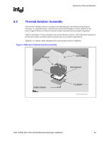
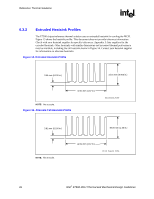
Reference Thermal Solutions R 6.3 Thermal Solution Assembly The reference thermal solution is a passive extruded heatsink with thermal and mechanical interfaces. It is attached using a clip with each end hooked through an anchor soldered to the board. Figure 9 shows the reference thermal solution assembly and associated components. Figure 9 and Figure 10 show alternate views of the reference solution. Full mechanical drawings of the thermal solution assembly and the heatsink clip are provided in Appendix B. Appendix A contains vendor information for each thermal solution component. Figure 9. Reference Thermal Solution Assembly Heatsin Thermal Anchored Mechanical Solder-Down FC-BGA ref_therm_solution_assy Intel® E7500 MCH Thermal and Mechanical Design Guidelines 23
-
 1
1 -
2
-
3
-
4
-
5
-
6
-
7
-
8
-
9
-
10
-
11
-
12
-
13
-
14
-
15
-
16
-
17
-
 18
18 -
 19
19 -
 20
20 -
 21
21 -
 22
22 -
 23
23 -
 24
24 -
 25
25 -
 26
26 -
 27
27 -
 28
28 -
29
-
30
-
31
-
32
-
33
-
34
-
35
 |
 |
