Intel E7500 Design Guide - Page 28
Clip Retention Anchors, Board Level Component Keep-out Dimensions
 |
View all Intel E7500 manuals
Add to My Manuals
Save this manual to your list of manuals |
Page 28 highlights
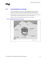
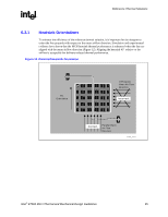
Reference Thermal Solutions R 6.3.6 Clip Retention Anchors For E7500 chipset-based platforms that have very limited board space, a clip retention anchor has been developed to minimize the impact of clip retention on the board. It is based on a standard three-pin jumper and is soldered to the board like any common through-hole header. A new anchor design is available with 45° bent leads to increase the anchor attach reliability over time. See Appendix A for the part number and supplier information. 6.3.7 Board Level Component Keep-out Dimensions The locations of hole patterns and keep-out zones for the reference thermal solution are shown in Figure 16 and Figure 17. Figure 16. Heatsink Retention Mechanism Layout 2.218 2.398 MCH 2x 1.199 NOTES: 1. Dimensions are in inches. 2. Not to scale. 2x 1.109 850_Anchor_Lay 28 Intel® E7500 MCH Thermal and Mechanical Design Guidelines
-
 1
1 -
2
-
3
-
4
-
5
-
6
-
7
-
8
-
9
-
10
-
11
-
12
-
13
-
14
-
15
-
16
-
17
-
18
-
19
-
20
-
21
-
22
-
 23
23 -
 24
24 -
 25
25 -
 26
26 -
 27
27 -
 28
28 -
 29
29 -
 30
30 -
 31
31 -
 32
32 -
 33
33 -
34
-
35
 |
 |
