Intel E7500 Design Guide - Page 11
Packaging Technology
 |
View all Intel E7500 manuals
Add to My Manuals
Save this manual to your list of manuals |
Page 11 highlights
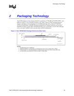
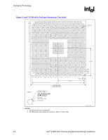
Packaging Technology R 2 Packaging Technology The E7500 chipset consists of three individual components: E7500 MCH, 82870P2 P64H2, and 82801CA ICH3-S. The E7500 MCH utilizes a 42.5 mm, 6-layer FC-BGA package shown in Figure 3 and Figure 2. For information on the P64H2 package, refer to the Intel® 82870P2 PCI/PCI-X 64-bit Hub 2 (P64H2) Thermal and Mechanical Design Guidelines and the Intel® 82870P2 PCI/PCI-X 64-bit Hub 2 (P64H2) Datasheet. For information on the ICH3-S package, refer to the Intel® 82801CA I/O Controller Hub 3 (ICH3-S) Datasheet. Figure 2. Intel® E7500 MCH Package Dimensions (Side View) 1.940 ± 0.150 mm Die Substrate 1.10 ± 0.10 mm 0.60 ± 0.10 mm Seating Plane 0.20 -C- See note 3. Package_Dimensions_Side NOTES: 1. All dimensions are in millimeters. 2. Substrate thickness and package overall height are thicker than standard 492-L PBGA. 3. Primary datum -C- and seating plane are defined by the spherical crowns of the solder balls. 4. All dimensions and tolerances conform to ANSI Y14.5M-1982. Intel® E7500 MCH Thermal and Mechanical Design Guidelines 11
-
 1
1 -
2
-
3
-
4
-
5
-
 6
6 -
 7
7 -
 8
8 -
 9
9 -
 10
10 -
 11
11 -
 12
12 -
 13
13 -
 14
14 -
 15
15 -
 16
16 -
17
-
18
-
19
-
20
-
21
-
22
-
23
-
24
-
25
-
26
-
27
-
28
-
29
-
30
-
31
-
32
-
33
-
34
-
35
 |
 |
