Intel E7500 Design Guide - Page 18
° Angle Attach Methodology
 |
View all Intel E7500 manuals
Add to My Manuals
Save this manual to your list of manuals |
Page 18 highlights
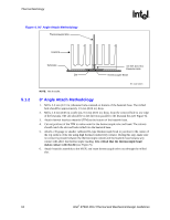
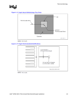
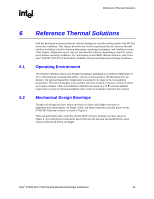
Thermal Metrology R Figure 4. 90° Angle Attach Methodology Thermocouple Wire Heatsink 5.1.2 Substrate Die 3.3 mm (0.13 in.) Diameter Hole Thermocouple Bead 90° Angle Attach NOTE: Not to scale. 0° Angle Attach Methodology 1. Mill a 3.3 mm (0.13 in.) diameter hole centered on bottom of the heatsink base. The milled hole should be approximately 1.5 mm (0.06 in.) deep. 2. Mill a 1.3 mm (0.05 in.) wide slot, 0.5 mm (0.02 in.) deep, from the centered hole to one edge of the heatsink. The slot should be in the direction parallel to the heatsink fins (see Figure 6). 3. Attach thermal interface material (TIM) to the bottom of the heatsink base. 4. Cut out portions of the TIM to make room for the thermocouple wire and bead. The cutouts should match the slot and hole milled into the heatsink base. 5. Attach a 36 gauge or smaller calibrated K-type thermocouple bead or junction to the center of the top surface of the die using high thermal conductivity cement. During this step, make sure no contact is present between the thermocouple cement and the heatsink base because any contact will affect the thermocouple reading. It is critical that the thermocouple bead makes contact with the die (see Figure 5). 6. Attach heatsink assembly to the MCH, and route thermocouple wires out through the milled slot. 18 Intel® E7500 MCH Thermal and Mechanical Design Guidelines
-
 1
1 -
2
-
3
-
4
-
5
-
6
-
7
-
8
-
9
-
10
-
11
-
12
-
 13
13 -
 14
14 -
 15
15 -
 16
16 -
 17
17 -
 18
18 -
 19
19 -
 20
20 -
 21
21 -
 22
22 -
 23
23 -
24
-
25
-
26
-
27
-
28
-
29
-
30
-
31
-
32
-
33
-
34
-
35
 |
 |
