Intel E7500 Design Guide - Page 4
s, Tables
 |
View all Intel E7500 manuals
Add to My Manuals
Save this manual to your list of manuals |
Page 4 highlights
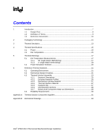
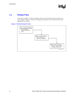
R Figures Figure 1. Thermal Design Process 8 Figure 2. Intel® E7500 MCH Package Dimensions (Side View 11 Figure 3. Intel® E7500 MCH Package Dimensions (Top View 12 Figure 4. 90° Angle Attach Methodology 18 Figure 5. 0° Angle Attach Methodology (Top View 19 Figure 6. 0° Angle Attach Heatsink Modifications 19 Figure 7. Thermal Solution Decision Flowchart 20 Figure 8. Reference Heatsink Volumetric Envelope for the Intel® MCH 22 Figure 9. Reference Thermal Solution Assembly 23 Figure 10. Reference Thermal Solution Assembly (Side View 24 Figure 11. Reference Thermal Solution (Top View 24 Figure 12. Preferred Heatsink Orientation 25 Figure 13. Extruded Heatsink Profile 26 Figure 14. Alternate Tall Heatsink Profile 26 Figure 15. Heatsink Mechanical Gasket, Optional Two-Piece 27 Figure 16. Heatsink Retention Mechanism Layout 28 Figure 17. Retention Mechanism Component Keep-out Zones 29 Figure 18. Intel® MCH Heatsink Assembly 34 Figure 19. Intel® MCH Heatsink Clip 35 Tables Table 1. Intel® E7500 MCH Thermal Specifications 15 Table 2. Reliability Requirements 30 Table 3. Complete Thermal Solution Kits 31 Table 4. Extruded Heatsinks 31 Table 5. Interface Materials 32 Table 6. Attach Hardware 32 4 Intel® E7500 MCH Thermal and Mechanical Design Guidelines
-
 1
1 -
 2
2 -
 3
3 -
 4
4 -
 5
5 -
 6
6 -
 7
7 -
 8
8 -
 9
9 -
 10
10 -
11
-
12
-
13
-
14
-
15
-
16
-
17
-
18
-
19
-
20
-
21
-
22
-
23
-
24
-
25
-
26
-
27
-
28
-
29
-
30
-
31
-
32
-
33
-
34
-
35
 |
 |
