Intel E7500 Design Guide - Page 12
Intel, E7500 MCH Package Dimensions Top View
 |
View all Intel E7500 manuals
Add to My Manuals
Save this manual to your list of manuals |
Page 12 highlights
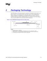
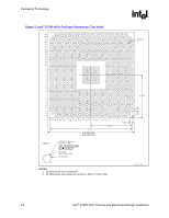
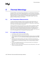
Packaging Technology R Figure 3. Intel® E7500 MCH Package Dimensions (Top View) AN AM AL Detail A AK AJ AH AG AF AE AD AC AB AA Y W V U T R P N M L K J 21.250 H G F E E C B 1.270 A 33 32 31 30 29 28 27 26 25 24 23 22 21 20 19 18 17 16 15 14 13 12 11 10 9 8 7 6 5 4 3 2 1 1.270 20.320 40.640 2x 42.500 ±0.100 0.200 A B Detail A Solder Resist Opening (n)x 0.650 ± 0.040 00.200 L C A S B 00.071 L C Metal Edge (n)x 0.790 ± 0.025 (n)x 0.025 Min NOTES: 1. All dimensions are in millimeters. 2. All dimensions and tolerances conform to ANSI Y14.5M-1982. MCH_Pkg_TopView 12 Intel® E7500 MCH Thermal and Mechanical Design Guidelines
-
 1
1 -
2
-
3
-
4
-
5
-
6
-
 7
7 -
 8
8 -
 9
9 -
 10
10 -
 11
11 -
 12
12 -
 13
13 -
 14
14 -
 15
15 -
 16
16 -
 17
17 -
18
-
19
-
20
-
21
-
22
-
23
-
24
-
25
-
26
-
27
-
28
-
29
-
30
-
31
-
32
-
33
-
34
-
35
 |
 |

Packaging Technology
R
12
Intel
®
E7500 MCH Thermal and Mechanical Design Guidelines
Figure 3. Intel
®
E7500 MCH Package Dimensions (Top View)
AN
AM
AL
AK
AJ
AH
AG
AF
AE
AD
AC
AB
AA
Y
W
V
U
T
R
P
N
M
L
K
J
H
G
F
E
E
C
B
A
10
16
20
3
5
7
9
11
13
15
19
4
6
18
8
12
14
22
21
24
23
26
25
28
27
30
29
31
32
(n)x 0.025 Min
Metal Edge
(n)x
0.790 ± 0.025
Solder Resist Opening
(n)x 0.650 ± 0.040
Detail A
00.071
L
C
00.200
L
C
A
S
B
33
1
2
1.270
20.320
40.640
2x 42.500 ±0.100
0.200
A
B
1.270
21.250
Detail A
MCH_Pkg_TopView
17
NOTES:
1. All dimensions are in millimeters.
2.
All dimensions and tolerances conform to ANSI Y14.5M–1982.