Intel E7500 Design Guide - Page 17
Thermal Metrology
 |
View all Intel E7500 manuals
Add to My Manuals
Save this manual to your list of manuals |
Page 17 highlights
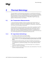
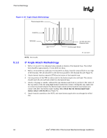
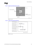
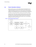
Thermal Metrology R 5 5.1 5.1.1 Thermal Metrology The system designer must make temperature measurements to accurately determine the thermal performance of the system. Intel has established guidelines for proper techniques of measuring the MCH die temperature. Section 5.1 provides guidelines on how to accurately measure the MCH die temperatures. Section 5.2 contains information on running an application program that will emulate anticipated maximum thermal design power. The flowchart in Figure 7 offers useful guidelines for thermal performance and evaluation. Die Temperature Measurements To ensure functionality and reliability, the MCH is specified for proper operation when Tdie is maintained at or below their respective maximum temperatures listed in Table 1. The surface temperature at the geometric center of the die corresponds to Tdie. Measuring Tdie requires special care to ensure an accurate temperature measurement. Temperature differences between the temperature of a surface and the surrounding local ambient air can introduce error in the measurements. The measurement errors could be due to a poor thermal contact between the thermocouple junction and the surface of the package, heat loss by radiation and/or convection, conduction through thermocouple leads, or contact between the thermocouple cement and the heatsink base (if a heatsink is used). To minimize these measurement errors, the following approaches are recommended for thermocouple attach. 90° Angle Attach Methodology 1. Use 36 gauge or smaller diameter K-type thermocouples. 2. Ensure that the thermocouple has been properly calibrated. 3. Attach the thermocouple bead or junction to the top surface of the die in the center using high thermal conductivity cement. It is critical that the thermocouple bead makes contact with the die. 4. The thermocouple should be attached at a 90° angle if no interference exists between the thermocouple wire and retention mechanism (see Figure 4). This is the preferred method and is recommended for use with both bare packages as well as packages employing a thermal solution. 5. The hole size through the heatsink base to route the thermocouple wires out should be no larger than 3.3 mm (0.13 in.) in diameter. 6. Make sure no contact exists between the thermocouple cement and heatsink base. This contact will affect the thermocouple reading. Intel® E7500 MCH Thermal and Mechanical Design Guidelines 17
-
 1
1 -
2
-
3
-
4
-
5
-
6
-
7
-
8
-
9
-
10
-
11
-
 12
12 -
 13
13 -
 14
14 -
 15
15 -
 16
16 -
 17
17 -
 18
18 -
 19
19 -
 20
20 -
 21
21 -
 22
22 -
23
-
24
-
25
-
26
-
27
-
28
-
29
-
30
-
31
-
32
-
33
-
34
-
35
 |
 |
