Intel E7500 Design Guide - Page 29
Retention Mechanism Component Keep-out Zones
 |
View all Intel E7500 manuals
Add to My Manuals
Save this manual to your list of manuals |
Page 29 highlights
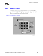
Reference Thermal Solutions R Figure 17. Retention Mechanism Component Keep-out Zones 0.896 0.070" Component Keepout 0.345 0.120 2x 0.060 0.225 (0.345) 0.100" Component Keepout 1.156 0.170 (0.165) Detail A 0.165 0.173 0.345 0.083 2x 0.038 Plated Through Hole 0.200 0.100 See Detail A 0.100 Component Keepout 2x 0.056 Trace Keepout NOTES: 1. Dimensions are in inches. 2. Not to scale. 850_Keepout_Zone Intel® E7500 MCH Thermal and Mechanical Design Guidelines 29
-
 1
1 -
2
-
3
-
4
-
5
-
6
-
7
-
8
-
9
-
10
-
11
-
12
-
13
-
14
-
15
-
16
-
17
-
18
-
19
-
20
-
21
-
22
-
23
-
 24
24 -
 25
25 -
 26
26 -
 27
27 -
 28
28 -
 29
29 -
 30
30 -
 31
31 -
 32
32 -
 33
33 -
 34
34 -
35
 |
 |

Reference Thermal Solutions
R
Intel
®
E7500 MCH Thermal and Mechanical Design Guidelines
29
Figure 17. Retention Mechanism Component Keep-out Zones
850_Keepout_Zone
0.896
0.345
0.120
1.156
0.170
(0.165)
0.100
0.225
2x
0.060
(0.345)
See Detail A
0.070" Component
Keepout
0.100" Component
Keepout
0.165
0.100
0.200
0.173
0.345
0.083
2x
0.038
Plated Through Hole
Component Keepout
Detail A
2x
0.056
Trace Keepout
NOTES:
1. Dimensions are in inches.
2. Not to scale.