Intel MFSYS25 User Guide
Intel MFSYS25 - AXXPSU 1000W Power Supply Module Manual
 |
UPC - 735858196901
View all Intel MFSYS25 manuals
Add to My Manuals
Save this manual to your list of manuals |
Intel MFSYS25 manual content summary:
- Intel MFSYS25 | User Guide - Page 1
Intel® Modular Server System User Guide A Guide for Technically Qualified Assemblers of Intel® Identified Subassemblies/Products Intel Order Number D90833-018 - Intel MFSYS25 | User Guide - Page 2
injury or death may occur. Intel® may make changes to specifications and product descriptions at any time, without notice. Intel® server boards contain a number of high-density VLSI and power delivery components that need adequate airflow for cooling. Intel®'s own chassis are designed and tested to - Intel MFSYS25 | User Guide - Page 3
components such as the fans, power supplies, hard drives, compute modules, and other components. Chapter 3 provides instructions and information on using the modular server system. This includes information for powering on and powering off the modular server system and installing an operating - Intel MFSYS25 | User Guide - Page 4
iv Intel® Modular Server System User Guide - Intel MFSYS25 | User Guide - Page 5
todas las declaraciones de seguridad y precaución de este documento antes de realizar cualquiera de las instrucciones. Vea Intel® Server Boards and Server Chassis Safety Information en: http://support.intel.com/support/motherboards/server/sb/cs-010770.htm Intel® Modular Server System User Guide v - Intel MFSYS25 | User Guide - Page 6
Reinstalling enclosure cover: To protect internal components and for proper cooling and airflow, the compute module should not be inserted into the chassis with the cover removed; operating it without the enclosure cover in place can damage system parts. vi Intel® Modular Server System User Guide - Intel MFSYS25 | User Guide - Page 7
the Management Module 21 Installing and Removing an Ethernet Switch Module 23 Installing an Ethernet Switch Module 23 Removing an Ethernet Switch Module 24 Installing and Removing a Storage Control Module 26 Installing a Storage Control Module 26 Intel® Modular Server System User Guide vii - Intel MFSYS25 | User Guide - Page 8
® Compute Module View ...67 Storage Configuration ...72 Intel® Gigabit Ethernet Switch Module 1 and 2 91 Chassis Back ...97 Intel® Storage Control Module 1 and 2 98 Intel® Management Module ...102 Intel® Modular Server Fans and Power Supplies 105 viii Intel® Modular Server System User Guide - Intel MFSYS25 | User Guide - Page 9
133 Restore System Settings ...135 Access Online Help ...137 Log Out from the Intel® Modular Server Control 137 Troubleshooting ...139 First Steps Checklist ...139 Specific Issues and Corrective Actions 139 Chassis Fan Module Not Functioning 140 Cannot Connect to the Management Module 140 Cannot - Intel MFSYS25 | User Guide - Page 10
172 Power and Electrical Warnings 173 Access Warnings ...173 Electrostatic Discharge (ESD 174 Other Hazards ...174 Deutsch ...175 Sicherheitshinweise für den Server 175 el acceso al sistema 188 Descarga electrostática (ESD 189 Otros peligros ...189 x Intel® Modular Server System User Guide - Intel MFSYS25 | User Guide - Page 11
Module 50 Figure 38. Removing Hard Drive from a Drive Carrier 51 Figure 39. Installing an Intel® Compute Module 52 Figure 40. Removing an Intel® Compute Module 53 Figure 41. Connection using a switch 59 Figure 42. Connection using a cross-over cable 59 Intel® Modular Server System User Guide - Intel MFSYS25 | User Guide - Page 12
Intel® Gigabit Ethernet Switch Module View 92 Figure 60. Configure Ports Dialog Box 96 Figure 61. Advanced Configuration Screen 97 Figure 62. Chassis Back View 98 Figure 63. Intel® Storage Control Module View 99 Figure 64. Intel® Management Module xii Intel® Modular Server System User Guide - Intel MFSYS25 | User Guide - Page 13
Figure 90. Settings - Feature Activation 133 Figure 91. Settings - Firmware Update Screen 134 Figure 92. Settings - Restore System Settings 135 Figure 93. Online Help ...137 Intel® Modular Server System User Guide xiii - Intel MFSYS25 | User Guide - Page 14
xiv Intel® Modular Server System User Guide - Intel MFSYS25 | User Guide - Page 15
Tabs 102 Table 28. Health Icons ...104 Table 29. Management Module Action Menu 104 Table 30. Management Module Tabs 105 Table 31. Health Icons ...106 Table 32. Fans and Power Supplies Tabs 106 Table 33. Diagnostic LEDs...142 Table 34. NIC LEDs ...143 Intel® Modular Server System User Guide xv - Intel MFSYS25 | User Guide - Page 16
xvi Intel® Modular Server System User Guide - Intel MFSYS25 | User Guide - Page 17
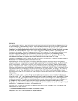
a features list, and diagrams showing the location of important components and connections on the server chassis. 1 2 3 4 5 6 7 8 9 10 11 12 13 14 1 I/O 2 1 2 ID 1 2 3 4 5 1 I/O 2 1 2 ID 6 Figure 1. Intel® Modular Server System MFSYS25 AF002423 Intel® Modular Server System User Guide 1 - Intel MFSYS25 | User Guide - Page 18
1 I/O 2 1 2 ID 1 I/O 2 1 2 ID Figure 2. Intel® Modular Server System MFSYS35 AF002661 Modular Server System Feature Overview Table 1 provides an overview of the modular server system configuration. 2 Intel® Modular Server System User Guide - Intel MFSYS25 | User Guide - Page 19
Server System MFSYS25 ships with the following items: Table 2. Intel® Modular Server System MFSYS25 Contents Quantity One One One One Description Chassis enclosure Intel® Management Module Intel® Gigabit Ethernet Switch Module Intel® Storage Control Module Intel® Modular Server System User Guide - Intel MFSYS25 | User Guide - Page 20
® Modular Server System MFSYS25V2 Contents Quantity One One One One 14 Two Two One Two Five Two One Description Chassis enclosure Intel® Management Module 2 Intel® Gigabit Ethernet Switch Module Intel® Storage Control Module 2.5" hard disk drive carriers 1000W Power Supply Modules Main Cooling Fan - Intel MFSYS25 | User Guide - Page 21
® Modular Server System MFSYS35 Contents Quantity One One One One Six Two Two One Two Five Two One Description Chassis enclosure Intel® Management Module Intel® Gigabit Ethernet Switch Module Intel® Storage Control Module 3.5" hard disk drive carriers 1000W Power Supply Modules Main Cooling Fan - Intel MFSYS25 | User Guide - Page 22
Intel® Compute Module MFS5520VI User Guide Available at: http://www.intel.com/p/en_US/support/highlights/server/mfs5520vi Intel® Modular Server System Quick Start User's Guide Provided in the product box or available for download at: http://www.intel.com/p/en_US/support/highlights/server/mfsys25 - Intel MFSYS25 | User Guide - Page 23
. Intel® Modular Server Control UI: The Intel® Management Module integrated management interface for the modular server system. For instructions and information, refer to the Intel® Modular Server System User Guide. Available at: http://www.intel.com/p/en_US/support/highlights/server/mfsys25 Major - Intel MFSYS25 | User Guide - Page 24
6 on bottom] B Hard Disk Drive bay module with hot-swap 2.5-inch SAS hard disk drives (14) [HDD 1 on the upper left and HDD 14 on the lower right] C I/O cooling module D System Status LED Figure 3. Front View of Intel® Modular Server System MFSYS25 8 Intel® Modular Server System User Guide - Intel MFSYS25 | User Guide - Page 25
• Memory • Integrated Baseboard Management Controller • Network interface • Storage control module For more information, refer to the appropriate compute module Technical Product Specification and User Guide. Hard Disk Drive Bay Module The Intel® Modular Server System has an integrated hard disk - Intel MFSYS25 | User Guide - Page 26
characteristics, Intel validates specific hard disk drive types in the platforms. See the Intel® Modular Server System Tested Hardware and Operating System List for a list of qualified drives. I/O Cooling Module The I/O cooling module consists of six fans in a hot-swap module with power and status - Intel MFSYS25 | User Guide - Page 27
power supply includes two fans that provide cooling for hot-swap disk drives. All four power supply bays must be populated with either a power supply module or a power supply blank. The power supply blank has two fans that ensure proper system cooling. Intel® Modular Server System User Guide 11 - Intel MFSYS25 | User Guide - Page 28
switch module allows for network redundancy. Storage Control Module One or two hot-swap Intel® Storage Control Modules can be used for up to 14 hot-swap SAS hard drives in the Intel® Modular Server System MFSYS25 and up to 6 hot-swap SAS/SATA hard drives in the Intel® Modular Server System MFSYS35 - Intel MFSYS25 | User Guide - Page 29
Green B Hard drive fault LED - Amber I/O Cooling Module C I/O cooling module power LED - Green D I/O cooling module fault LED - Amber Chassis E System Fault LED - Amber Figure 6. Intel® Modular Server System MFSYS25 Front Chassis Connectors and Indicators Intel® Modular Server System User Guide 13 - Intel MFSYS25 | User Guide - Page 30
Hard Drive Carrier A Hard drive power/activity LED - Green I/O Cooling Module B I/O cooling module power LED - Green C I/O cooling module fault LED - Amber Chassis D System Fault LED - Amber Figure 7. Intel® Modular Server System MFSYS35 Front Chassis Connectors and Indicators Compute Module - Intel MFSYS25 | User Guide - Page 31
Module I Power supply module power LED - Green J Power supply fault indicator LED - Amber Main Cooling Module N Main cooling module fault LED - Amber O Main cooling module power LED - Green Figure 8. Rear Chassis Connectors and Indicators AF002065 Intel® Modular Server System User Guide - Intel MFSYS25 | User Guide - Page 32
All indicator modes are described in "Diagnostic LED Information" on page 141. Rack Mount Options Your Intel® Modular Server System MFSYS25/MFSYS35 can be mounted into a 4-post fixed mount rack. 16 Intel® Modular Server System User Guide - Intel MFSYS25 | User Guide - Page 33
the system, DO NOT lift by the power supply or fan module handles. • All compute modules, hard drives, power supply modules, I/O modules, and cooling modules should be removed before placing the Intel® Modular Server System MFSYS25/MFSYS35 in a rack. Intel® Modular Server System User Guide 17 - Intel MFSYS25 | User Guide - Page 34
ID 1 2 3 4 5 1 I/O 2 1 2 ID 6 AF002418 Figure 9. Installing Temporary Handles The system can now be moved as required to aid in removal from packaging, installation of the remaining modules in the system, or installation of the system in a rack. 18 Intel® Modular Server System User Guide - Intel MFSYS25 | User Guide - Page 35
Secure the server system in the rack as described in the rail installation instructions. 7. Install all compute modules, hard drives, power supply modules, I/O modules, and cooling modules. Hot-Swap Module Installation and Removal Guidelines • The green color on components and labels in your chassis - Intel MFSYS25 | User Guide - Page 36
Replacing the Management Module The Intel® Modular Server System MFSYS25/MFSYS35 ships with a management module pre-installed in the middle bay of the rear of the chassis. The middle bay is dedicated to the management module and is labeled CMM. For the exact location of the management module bay, - Intel MFSYS25 | User Guide - Page 37
the Management Module To install the management module, follow these steps: 1. Review the safety and ESD information at the beginning of this manual and in the appendices. 2. Locate the management module bay and remove the module to be replaced. Intel® Modular Server System User Guide 21 - Intel MFSYS25 | User Guide - Page 38
of the retention lever engages with the module bay. B A AF002414 Figure 11. Installing the Management Module 5. Rotate the lever handle in toward the module bay until it is latched. 6. Reconnect the Ethernet management port to the management network. 22 Intel® Modular Server System User Guide - Intel MFSYS25 | User Guide - Page 39
Switch Module The Intel® Modular Server System MFSYS25/MFSYS35 ships with one Ethernet switch module pre-installed. Optionally, a second switch module may be installed in the second switch module bay. An ethernet switch module can only be installed in a module bay that is designed to support - Intel MFSYS25 | User Guide - Page 40
the retention latch (see letter "A" in Figure 13) to release the retention lever. 4. Rotate the lever out and away from the module bay (see letter "B" in Figure 13) and pull the module straight out the back of the chassis (see letter "C" in Figure 13). 24 Intel® Modular Server System User Guide - Intel MFSYS25 | User Guide - Page 41
C A B AF002413 Figure 13. Removing an Ethernet Switch Module 5. Install a filler panel or another Ethernet switch module in the switch module bay within two minutes. Intel® Modular Server System User Guide 25 - Intel MFSYS25 | User Guide - Page 42
Module The Intel® Modular Server System MFSYS25/MFSYS35 ships with one storage control module pre-installed. Optionally, a second storage control module may be installed in the open storage control module bay. A Storage Control module can only be installed in a module bay that is designed to support - Intel MFSYS25 | User Guide - Page 43
® Modular Server System, power off all compute modules prior to removing the Intel® Storage Control Module To remove a storage control module, follow these steps: 1. Review the safety and ESD information at the beginning of this manual and in the appendices. Intel® Modular Server System User Guide - Intel MFSYS25 | User Guide - Page 44
with a filler panel or another storage control module within two minutes. C A B AF002430 Figure 15. Removing a Storage Control Module 4. Install a filler panel or another storage control module in the storage control module bay within two minutes. 28 Intel® Modular Server System User Guide - Intel MFSYS25 | User Guide - Page 45
module (see letter "A" in Figure 16). B C A AF002563 Figure 16. Removing Top Cover from Storage Control Module 5. Slide the cover towards the rear of the storage control module (see letter "B" in Figure 16) and lift upward (see letter "C" in Figure 16). Intel® Modular Server System User Guide - Intel MFSYS25 | User Guide - Page 46
. 2. Remove the storage control module from the system. For instructions, see "Removing a Storage Control Module" on page 27. Warning: You must replace the storage control module with a filler panel or another storage control module within two minutes. 30 Intel® Modular Server System User Guide - Intel MFSYS25 | User Guide - Page 47
module (see letter "A" in Figure 18). B C A AF002563 Figure 18. Removing Top Cover from Storage Control Module 5. Slide the cover towards rear of the storage control module (see letter "B" in Figure 18) and lift upward (see letter "C" in Figure 18). Intel® Modular Server System User Guide - Intel MFSYS25 | User Guide - Page 48
Installing and Removing a Power Supply Module The Intel® Modular Server System MFSYS25/MFSYS35 ships with two power supply modules pre-installed. A single power supply is suitable to support the power requirement for the chassis, including fan modules, storage control module, switch module, storage - Intel MFSYS25 | User Guide - Page 49
remove a filler module, press the retention lever latch (see letter "A" in Figure 20) to release the filler module from the module bay. Slide the filler module out of the bay (see letter "B" in Figure 20). B A AF002420 Figure 20. Removing Filler Module Intel® Modular Server System User Guide 33 - Intel MFSYS25 | User Guide - Page 50
module, follow these steps: 1. Review the safety and ESD information at the beginning of this manual and in the appendices. 2. Locate the power supply module to be removed. 3. Remove the power cord from both the power supply module and the power source. 34 Intel® Modular Server System User Guide - Intel MFSYS25 | User Guide - Page 51
22. Removing a Power Supply Module 5. Replace the power supply module with a filler panel or another power supply module within two minutes. Replacing a Main Cooling Module The Intel® Modular Server System MFSYS25/MFSYS35 ships with two main cooling modules pre-installed at the back of the chassis - Intel MFSYS25 | User Guide - Page 52
(see letter "B" in Figure 23). Warning: Replace the cooling module with another cooling module within two minutes. B A AF002438 Figure 23. Removing a Main Cooling Module 5. Install another cooling module into the cooling module bay within two minutes. 36 Intel® Modular Server System User Guide - Intel MFSYS25 | User Guide - Page 53
Figure 24. Installing a Main Cooling Module Replacing the I/O Cooling Module The Intel® Modular Server System MFSYS25/MFSYS35 ships with one I/O cooling module pre-installed at the front of the chassis. For the exact location of the I/O Cooling Module in Intel® Modular Server System User Guide 37 - Intel MFSYS25 | User Guide - Page 54
• Intel® Modular Server System MFSYS25, see Figure 3 • Intel® Modular Server System MFSYS35, see Figure 4. Removing the I/O Cooling Module To remove the I/O cooling module, follow these steps: 1. Review the safety and ESD information at the beginning of this manual and in the appendices. 2. Locate - Intel MFSYS25 | User Guide - Page 55
. Installing an I/O Cooling Module Installing and Removing Hard Drives The Intel® Modular Server System MFSYS25/MFSYS35 provides storage for installed compute modules by way of an on-board storage bay combined with a storage management module. The on-board storage bay supports the installation of up - Intel MFSYS25 | User Guide - Page 56
letter "B" in Figure 27). A B 1 2 3 4 5 6 7 8 9 10 11 12 13 14 AF002425 Figure 27. Removing a 2.5-inch Drive Carrier from a Drive Bay Module 3. With a Phillips* screwdriver, remove the four screws securing the filler panel to the drive carrier. 40 Intel® Modular Server System User Guide - Intel MFSYS25 | User Guide - Page 57
hard drive to the holes in the drive carrier (see letter "A" in Figure 28) and attach it to the drive carrier using the four screws removed in the previous step (see letter "B" in Figure 28). A B AF002428 Figure 28. Installing Hard Drive into Drive Carrier Intel® Modular Server System User Guide - Intel MFSYS25 | User Guide - Page 58
in the open position (see letter "A" in Figure 30), carefully slide the drive carrier into the drive bay module until it is fully seated and the retaining lever starts to engage. Press firmly to latch the retaining lever (see letter "B" in Figure 30). 42 Intel® Modular Server System User Guide - Intel MFSYS25 | User Guide - Page 59
1. Review the safety and ESD information at the beginning of this manual and in the appendices. 2. To avoid data corruption, ensure that the drive you intend to remove is not online and actively providing data storage to any of the installed compute modules. Intel® Modular Server System User Guide - Intel MFSYS25 | User Guide - Page 60
drive bay module (see letter "A" in Figure 31). Remove the drive carrier from the drive bay module (see letter "B" in Figure 31). A B 1 2 3 4 5 6 7 8 9 10 11 12 13 14 AF002425 Figure 31. Removing a 2.5-inch Drive Carrier from the Drive Bay Module 44 Intel® Modular Server System User Guide - Intel MFSYS25 | User Guide - Page 61
the hard drive to the drive carrier (see letter "A" in Figure 32). Lift the hard drive from the carrier (see letter "B" in Figure 32) and store the hard drive in an anti-static container or bag. B A AF002429 Figure 32. Removing Hard Drive from a Drive Carrier Intel® Modular Server System User Guide - Intel MFSYS25 | User Guide - Page 62
ensure proper system cooling. Installing a 3.5-inch Hard Drive into the Storage Bay To install a 3.5-inch hard drive into the storage bay, follow these steps: 1. Review the safety and ESD information at the beginning of this manual and in the appendices. 46 Intel® Modular Server System User Guide - Intel MFSYS25 | User Guide - Page 63
drive carrier from the drive bay module (see letter "B" in Figure 34). B A AF002662 Figure 34. Removing a 3.5-inch Drive Carrier from the Drive Bay Module 3. With a Phillips* screwdriver, remove the four screws securing the filler panel to the drive carrier. Intel® Modular Server System User Guide - Intel MFSYS25 | User Guide - Page 64
hard drive to the holes in the drive carrier (see letter "A" in Figure 35) and attach it to the drive carrier using the four screws removed in the previous step (see letter "B" in Figure 35). A B AF00317 Figure 35. Installing Hard Drive into Drive Carrier 48 Intel® Modular Server System User Guide - Intel MFSYS25 | User Guide - Page 65
1. Review the safety and ESD information at the beginning of this manual and in the appendices. 2. To avoid data corruption, ensure that the drive you intend to remove is not online and actively providing data storage to any of the installed compute modules. Intel® Modular Server System User Guide - Intel MFSYS25 | User Guide - Page 66
to release the drive carrier from the drive bay module (see letter "A" in Figure 37). Remove the drive carrier from the drive bay module (see letter "B" in Figure 37). B A AF002662 Figure 37. Removing a 3.5-inch Drive Carrier from the Drive Bay Module 50 Intel® Modular Server System User Guide - Intel MFSYS25 | User Guide - Page 67
hot-swap hard drive or a filler blank in the drive carrier. 6. Install the drive carrier into the empty drive bay module within two minutes; this step is required to maintain proper airflow throughout the chassis and to ensure proper system cooling. Intel® Modular Server System User Guide 51 - Intel MFSYS25 | User Guide - Page 68
(see letter "B" in Figure 39). 1 2 3 4 5 6 7 8 9 10 11 12 13 14 1 I/O 2 1 2 ID 1 2 3 4 B 5 6 A 1 I/O 2 1 2 ID A Figure 39. Installing an Intel® Compute Module 4. Close the release handles on the front of the compute module. AF002431 52 Intel® Modular Server System User Guide - Intel MFSYS25 | User Guide - Page 69
A AF002432 Figure 40. Removing an Intel® Compute Module 4. Place either a filler or another compute module in the bay within two minutes. This step is required to maintain proper airflow throughout the server system and to ensure proper system cooling. Intel® Modular Server System User Guide 53 - Intel MFSYS25 | User Guide - Page 70
54 Intel® Modular Server System User Guide - Intel MFSYS25 | User Guide - Page 71
Intel® Modular Server System MFSYS25/MFSYS35 does not have a power switch. When the chassis has at least one power supply with power cord plugged into an appropriate electrical outlet, standby power is available. With standby current, a user can remotely connect to the management module and/or power - Intel MFSYS25 | User Guide - Page 72
remove power from the Intel® Modular Server System MFSYS25/MFSYS35, you must first properly power down all compute modules. Next, disconnect all power cables from the power source. For more information on powering down the compute module(s), refer to the Intel® Compute Module MFS50000SI User Guide - Intel MFSYS25 | User Guide - Page 73
, system event logs, storage allocation and system configuration reports. • Easily view current status for all hardware components (servers, hard drives, switch modules, storage control modules, management module, cooling modules, and power modules). Intel® Modular Server System User Guide 57 - Intel MFSYS25 | User Guide - Page 74
network, or if the default management module IP address cannot be accessed in the installed network environment. For more information, see "IP Configuration" on page 118. • View modular server system health and additional required actions (recommended): 58 Intel® Modular Server System User Guide - Intel MFSYS25 | User Guide - Page 75
the remote system, ensure all hardware components (servers, hard drives, switch modules, storage control modules, the management module, cooling modules, and power modules) are installed in the Intel® Modular Server System. Option 1: Connect the client system and the Intel® Management Module to an - Intel MFSYS25 | User Guide - Page 76
is enabled for the system. This default administrator account provides access to all available management configuration settings and actions. User Account information: - Username: admin - Password: admin Note: Username and password are case sensitive. 60 Intel® Modular Server System User Guide - Intel MFSYS25 | User Guide - Page 77
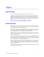
A B C AF002066 A Enter Management Module IP Address, 192.168.150.150 B Enter Default Username (admin) C Enter Default Password (admin) Figure 43. Intel® Modular Server Control Login Intel® Modular Server System User Guide 61 - Intel MFSYS25 | User Guide - Page 78
configuration screens are designed to present all available information and actions for a selected system component in the main body of the interface. Left Navigation Top Menu Main Body AF002459 Figure 44. Intel® Modular Server Control General Layout 62 Intel® Modular Server System User Guide - Intel MFSYS25 | User Guide - Page 79
Figure 8 illustrates the layout and types of information presented on the system configuration screens. QR G D ABC I E O P F J N S L K H M AF002067 Figure 45. Intel® Modular Server Control Configuration Screen Layout Intel® Modular Server System User Guide 63 - Intel MFSYS25 | User Guide - Page 80
Interactive visual representation of the current state of the system hardware. By selecting a system component from the chassis graphic, the content changes in the main body to display all available actions and information for the selected component. 64 Intel® Modular Server System User Guide - Intel MFSYS25 | User Guide - Page 81
over icon to view component summary information. R Global Hot Spare Icon - indicates hard drives that have been designated as global hot spares. Hover over icon to view component summary information. S Server is powered off. Ready for Transport Intel® Modular Server System User Guide 65 - Intel MFSYS25 | User Guide - Page 82
current health, state and component description is displayed in a pop-up box. To access the Chassis Front view, click the Chassis Front tab in the top menu. By default, no components are selected on the chassis in this view. Figure 46. Chassis Front View 66 Intel® Modular Server System User Guide - Intel MFSYS25 | User Guide - Page 83
switch modules). When a system component is selected, the content in the action box, help box and informational tabs change to reflect the current actions and information for the selected component. Intel® Compute Module View The Intel® Modular Server System MFSYS25/MFSYS35 supports up to six Intel - Intel MFSYS25 | User Guide - Page 84
are displayed to the right of the system graphic. For a description of these actions, refer to the following table. Action Menu Item Power On (if Off) Table 10. Server Action Menu Description Allows the user to remotely power on the selected server. 68 Intel® Modular Server System User Guide - Intel MFSYS25 | User Guide - Page 85
type of action first (power on, power off, reset). Then select the servers to apply the action. CAUTION: To avoid potential data loss when selecting power off the Graceful Shutdown option is recommended to shut down applications and the operating system. Intel® Modular Server System User Guide 69 - Intel MFSYS25 | User Guide - Page 86
network or performance problems on the client computer. b. Select Mouse Mode. Choose Absolute if the remote server is running the Microsoft Windows* operating system. Choose Relative if the remote server is running the Linux* operating system. 70 Intel® Modular Server System User Guide - Intel MFSYS25 | User Guide - Page 87
KVM session in a new window. The following KVM window is displayed. Figure 48. Server Action - Remote KVM & CD 7. Select Start Redirection from the Redirection menu. If the CD into the remote console's CD-ROM drive and select CD from the Devices menu. Intel® Modular Server System User Guide 71 - Intel MFSYS25 | User Guide - Page 88
The Intel® Modular Server System MFSYS25 supports up to 14 2.5-inch SAS drives and the Intel® Modular Server System MFSYS35 supports up to six 3.5-inch SAS/SATA drives. These drives are shared between all compute modules. The physical disk drives are not directly connected to the compute modules. To - Intel MFSYS25 | User Guide - Page 89
the Storage Pool Actions menu. The following dialog box appears. Figure 50. Create Storage Pool Dialog Box 3. Enter a name or label for the storage pool. 4. Select the physical hard drives that are to be grouped together to create a single storage pool. Intel® Modular Server System User Guide 73 - Intel MFSYS25 | User Guide - Page 90
informational tabs update to provide all available actions and information for the selected storage pool. Current health and product summary is quickly available by moving the mouse over the Health/Information icon located on the selected storage pool. 74 Intel® Modular Server System User Guide - Intel MFSYS25 | User Guide - Page 91
The following image displays information for the storage pool. Figure 52. Storage Pool Screen Health Icons The health icons are displayed on the graphical For information about accessing the Event Log, see "Events" on page 109.) Information OK Intel® Modular Server System User Guide 75 - Intel MFSYS25 | User Guide - Page 92
the hard drive ID LED, which enables easy onsite identification of the drives included in the selected storage pool. A virtual drive is assigned a name, RAID level, size and server. Once a virtual drive is created, an operating system can be installed. 76 Intel® Modular Server System User Guide - Intel MFSYS25 | User Guide - Page 93
and needs to be recovered by rebuilding with the hot-spare drive. Storage Pool Details The tabs displayed below the system graphic provide detailed information on the selected storage pool. For a description of these tabs, refer to the following table. Intel® Modular Server System User Guide 77 - Intel MFSYS25 | User Guide - Page 94
the virtual drive will be indistinguishable from the local physical drive on the server (if installed). • If the Intel® Shared LUN feature is activated and the operating system supports sharing LUNs, a virtual drive can be assigned to two or more servers. 78 Intel® Modular Server System User Guide - Intel MFSYS25 | User Guide - Page 95
control module for the virtual drive. 8. Assign or map the virtual drive to a server. A virtual drive can be assigned to any of the six server slots. A server does not have to be present in the Intel® Modular Server System MFSYS25/MFSYS35 for selection. Intel® Modular Server System User Guide 79 - Intel MFSYS25 | User Guide - Page 96
drive is created and selected, the action menu and tabs change to display all available actions and details for the selected virtual drive. The following image shows the storage screen with a virtual drive selected. Figure 54. Virtual Drive Screen 80 Intel® Modular Server System User Guide - Intel MFSYS25 | User Guide - Page 97
health status description as you move the mouse cursor over the health icon: • Degraded: The virtual drive RAID array is available but has lost one or more disks. The virtual drive will be rebuilt automatically if a global or dedicated spare is available. Intel® Modular Server System User Guide 81 - Intel MFSYS25 | User Guide - Page 98
is handled by the multipath driver on the host operating system. Virtual Drive Details The tabs displayed below the system graphic provide detailed information on the selected virtual drive. For a description of these tabs, refer to the following table. 82 Intel® Modular Server System User Guide - Intel MFSYS25 | User Guide - Page 99
operating system boots, all five virtual drives will be available for use. To assign a virtual drive to a server, follow these steps: 1. From the Storage view, select a virtual drive. 2. Choose Assign from the action menu. The following dialog box appears. Intel® Modular Server System User Guide - Intel MFSYS25 | User Guide - Page 100
the virtual drive. It is recommended to power off the compute module before reassigning virtual drives to another compute module. However, it is safe to make new assignments to compute modules regardless of whether the compute module is powered on or off. 84 Intel® Modular Server System User Guide - Intel MFSYS25 | User Guide - Page 101
available by moving the mouse over the Health/ Information icon located on the selected hard drive. Note: For drives that are included in a storage pool, limited drive details are also displayed on the physical drive tab for the assigned storage pool. Intel® Modular Server System User Guide 85 - Intel MFSYS25 | User Guide - Page 102
Figure 57. Physical Drives 86 Intel® Modular Server System User Guide - Intel MFSYS25 | User Guide - Page 103
). • Stale: The drive was at one time part of a storage pool, but was taken offline by an error or was transported without being installed, and is no longer required by the storage pool. You may keep the drive in the stale state to preserve the data (for Intel® Modular Server System User Guide 87 - Intel MFSYS25 | User Guide - Page 104
hot-spare status and sets the drive to available. Available drives can be assigned to existing storage pools, new storage pools or used as hot-spare drives. Cancel Hot Spare is present if a drive role is assigned as either a global or dedicated hot spare. 88 Intel® Modular Server System User Guide - Intel MFSYS25 | User Guide - Page 105
storage pools or virtual included in a storage pool) drives. Physical Drive Help To quickly access additional help regarding physical drive actions and tabs, click on the Get Help button in the Shared Drive help box located under the action box. Intel® Modular Server System User Guide 89 - Intel MFSYS25 | User Guide - Page 106
to all storage pools) or a dedicated hot-spare drive (assigned to a specific storage pool) and click Apply. Once the hot spare has been created, a successful action dialog will be displayed and the information icon will change to the hot spare icon, . 90 Intel® Modular Server System User Guide - Intel MFSYS25 | User Guide - Page 107
specific information and actions available for the selected switch module highlighted in green. The current health and product summary information is quickly available by moving the mouse over the Health/Information icon located on the selected switch module. Intel® Modular Server System User Guide - Intel MFSYS25 | User Guide - Page 108
Figure 59. Intel® Gigabit Ethernet Switch Module View Health Icons The health icons are displayed on the graphical representation of the component when the component is selected. 92 Intel® Modular Server System User Guide - Intel MFSYS25 | User Guide - Page 109
a third-party Advanced Switch Configuration interface in a new window to view all switch configuration options. Refer to the Intel® Gigabit Ethernet Switch AXXSW1GB User Guide for more information on how to use the Advanced Configuration Switch interface. Intel® Modular Server System User Guide 93 - Intel MFSYS25 | User Guide - Page 110
the Actions box. Configuring an Intel® Gigabit Ethernet Switch Intel® Gigabit Ethernet Switches come pre-configured with all available ports enabled in a single default VLAN. No additional configuration is required to connect the Intel® Modular Server System MFSYS25/MFSYS35 to a network. Two options - Intel MFSYS25 | User Guide - Page 111
or an existing VLAN number, since the Apply process creates the VLAN and also assigns the ports. The following image illustrates the Configure Ports dialog. Intel® Modular Server System User Guide 95 - Intel MFSYS25 | User Guide - Page 112
Ethernet Switch Module in a new window. This interface exposes all configuration settings for the switch. Configuration settings modified in either the Advanced Configuration or the Intel® Modular Server Control UI are displayed in both interfaces. 96 Intel® Modular Server System User Guide - Intel MFSYS25 | User Guide - Page 113
accurate visual view of the back of the chassis, which includes the management module, switch modules, storage control modules, power supplies and fans. This real-time view enables an IT state and component description is displayed in a pop-up box. Intel® Modular Server System User Guide 97 - Intel MFSYS25 | User Guide - Page 114
in the top menu. By default, no components are selected on the chassis in this view. Figure 62. Chassis Back View Intel® Storage Control Module 1 and 2 The Intel® Modular Server System MFSYS25/MFSYS35 contains at least one storage module in slot SCM1. A second storage module may be added to improve - Intel MFSYS25 | User Guide - Page 115
Figure 63. Intel® Storage Control Module View Health Icons The health icons are displayed on the graphical representation of the component when the component is selected. Intel® Modular Server System User Guide 99 - Intel MFSYS25 | User Guide - Page 116
Table 25. Status Messages Status Message Meaning Firmware update The SCM firmware update is in progress. in progress. default. The SCM is operational and this SCM is the secondary controller in a dual SCM configuration. The SCMs have redundancy. 100 Intel® Modular Server System User Guide - Intel MFSYS25 | User Guide - Page 117
remote reset of the selected Intel® Storage Control Module. Enable/Disable server access to the external expansion port on the selected storage control module. Additional external storage options are available to the server via the expansion port. Intel® Modular Server System User Guide 101 - Intel MFSYS25 | User Guide - Page 118
-specific information and available actions for the management module highlighted in green. The current health and product summary information is quickly available by moving the mouse over the Health/ Information icon located on the management module graphic. 102 Intel® Modular Server System User - Intel MFSYS25 | User Guide - Page 119
Figure 64. Intel® Management Module View Health Icons The health icons are displayed on the graphical representation of the component when the component is selected. Intel® Modular Server System User Guide 103 - Intel MFSYS25 | User Guide - Page 120
Enables remote reset of the selected management module. Intel® Management Module Details The tabs displayed below the system graphic provide detailed information for the management module. For a description of these tabs, refer to the following table. 104 Intel® Modular Server System User Guide - Intel MFSYS25 | User Guide - Page 121
over the Health/Information icon located on the selected component. Note: No actions are available for fans or power supplies. Health Icons The health icons are displayed on the graphical representation of the component when the component is selected. Intel® Modular Server System User Guide 105 - Intel MFSYS25 | User Guide - Page 122
, system configuration information, event logs, diagnostic information, storage resource allocation map, switch performance, and hardware and firmware inventory. The following reports are supported: Storage Layout, Events, Dashboard, and Diagnostics. 106 Intel® Modular Server System User Guide - Intel MFSYS25 | User Guide - Page 123
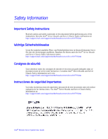
as a 25-GB RAID 0 drive. The second virtual drive is named "Marketing" and is configured as a 30-GB RAID 0 drive. • The virtual drive "Finance" is assigned to Server 1 as Drive 0. The virtual drive "Marketing" is assigned to Server 2 as Drive 0. Intel® Modular Server System User Guide 107 - Intel MFSYS25 | User Guide - Page 124
Figure 65. Storage Layout Graphical View 108 Intel® Modular Server System User Guide - Intel MFSYS25 | User Guide - Page 125
in the left navigation panel. The following features enable the IT administrator to quickly access specific information from the System Event Log screen: • Sort events: Sort the events in the table by ID, closed, it is no longer displayed on this screen. Intel® Modular Server System User Guide 109 - Intel MFSYS25 | User Guide - Page 126
displayed at the top of the screen next to the Rows drop-down list. Click on the page number to view additional events. Figure 67. System Event Log Screen Note: To view a history of events, select the event tab on each component screen. 110 Intel® Modular Server System User Guide - Intel MFSYS25 | User Guide - Page 127
is present or not present in the system, its current health and a component description. To view detailed information and available actions for any component, click the component name to be redirected to the specific component configuration screen. Intel® Modular Server System User Guide 111 - Intel MFSYS25 | User Guide - Page 128
meant to be used as a general purpose information screen, but only as a source of information that can be provided to support personnel for problem resolution. To access the Diagnostics screen, click Reports > Diagnostics in the left navigation panel. 112 Intel® Modular Server System User Guide - Intel MFSYS25 | User Guide - Page 129
Ethernet switch module, storage control module, fan, chassis, and server. The System Information Report generates a complete report about your system and the system settings (this does not include user account information). Clicking the System Information Report will download the service information - Intel MFSYS25 | User Guide - Page 130
Figure 71. Diagnostic Tests Figure 72. System Information Report Download 114 Intel® Modular Server System User Guide - Intel MFSYS25 | User Guide - Page 131
Figure 73. System Information Report Intel® Modular Server System User Guide 115 - Intel MFSYS25 | User Guide - Page 132
and hardware management. Storage Drive Caching Options Every physical hard drive in the chassis has an on-board cache. The cache generally improves the I/O performance of a drive by acting as a fast data buffer during large read and write operations. 116 Intel® Modular Server System User Guide - Intel MFSYS25 | User Guide - Page 133
situation, provide a power backup (such as an UPS) for the chassis. The backup power supply should be capable of and configured to trigger an orderly shutdown of each server in the chassis. Figure 75. Settings - Storage Caching Options Configuration Intel® Modular Server System User Guide 117 - Intel MFSYS25 | User Guide - Page 134
® Management Module host name and external network access, as well as view the internal configuration. The following is a description of the settings and information found in the IP Configuration tab: • Host Name: Change the management module host name. 118 Intel® Modular Server System User Guide - Intel MFSYS25 | User Guide - Page 135
only. To access the IP Configuration screen, click Settings > IP Configuration in the left navigation panel. The Intel® Modular Server Control IP Configuration screen similar to the following image is displayed. Figure 77. Settings - IP Configuration Intel® Modular Server System User Guide 119 - Intel MFSYS25 | User Guide - Page 136
to directly set the date and time or specify a network time server to set the date and time on the management module. The new date and time will be displayed once the management module is reset. Figure 78. Settings - System Date and Time Configuration 120 Intel® Modular Server System User Guide - Intel MFSYS25 | User Guide - Page 137
. 5. Click Save Changes. In the Update dialogue box Update and Reboot. This action will reset the management module to enable the changes to take effect. Steps to Add a Network Time Server 1. Click Settings > Date/Time in the left navigation panel. Intel® Modular Server System User Guide 121 - Intel MFSYS25 | User Guide - Page 138
. This action will reset the management module to enable the changes to take effect. Simple Network Management Protocol (SNMP) The Intel® Modular Server System MFSYS25/MFSYS35 supports Simple Network Management Protocol (SNMP). An IT administrator can view system configuration settings and health - Intel MFSYS25 | User Guide - Page 139
or disable SNMP v2. By default, this setting is set to enabled. The Intel® Modular Server System supports readonly access to system information via SNMP v2. To use SNMP v3, SNMP v2 does not need to be enabled; however, before changing this setting, you must verify that your management software does - Intel MFSYS25 | User Guide - Page 140
the Intel® Compute Module's power state (on/off) and identify LED (on/off). Read/write access does not enable an SNMP v3 user account to remotely configure the Intel® Modular Server System. Full hardware management and configuration is only supported via the Intel® Modular Server Control interface - Intel MFSYS25 | User Guide - Page 141
management users. Use this procedure if an outside SNMP tool has modified or deleted the internal-chassis management users. This procedure may take up to a minute to complete. To reactivate the SNMP v3 , go to the SNMP v3 settings screen. Figure 82. Reset SNMP v3 Intel® Modular Server System User - Intel MFSYS25 | User Guide - Page 142
the IT administrator to access the Intel® Module Server Control UI for initial configuration. It is recommended that the default administrator password is changed before adding the Intel® Modular Server System to the production network. The administrator password supports a maximum of 10 characters - Intel MFSYS25 | User Guide - Page 143
event severity and notification process. To configure an event policy, click Edit for a specific event. The Edit dialog box appears. Use the dialog box to change the severity of a specific event, as well as to select who to notify when the event occurs. Intel® Modular Server System User Guide 127 - Intel MFSYS25 | User Guide - Page 144
Figure 85. Settings - Event Policies Configuration Screen 128 Intel® Modular Server System User Guide - Intel MFSYS25 | User Guide - Page 145
address and control the email notification settings for each user account, see "User Accounts" on page 126 To configure the events that generate email notifications, see "Event Policies" on page 127. Figure 86. Email Notification Configuration Intel® Modular Server System User Guide 129 - Intel MFSYS25 | User Guide - Page 146
the Application Message Facility. 8. Select the Switch Message Facility. 9. Select the Storage Message Facility. 10. Select the Chassis Message Facility. 11. Click Save Changes to save the changes in the settings. Figure 87. SYSLOG Notification Setting 130 Intel® Modular Server System User Guide - Intel MFSYS25 | User Guide - Page 147
Users, Switch, and Storage from one chassis and import to a chassis with a similar configuration. Figure 88. Configuration Import /Export Language Option Setting The Intel® Modular Server for the online help. 3. Click Save Changes to save the changes. Intel® Modular Server System User Guide 131 - Intel MFSYS25 | User Guide - Page 148
use it: • Intel® Shared LUN Feature: The Intel® Shared LUN Feature allows two or more servers to share a virtual drive. This feature requires operating system support for sharing LUNs. • Intel® Modular Server Storage Management Pack Features: With the Intel® Modular Server Storage Management Pack - Intel MFSYS25 | User Guide - Page 149
the firmware for the entire system, this screen will display all currently installed component firmware versions, as well as current status. This will enable the IT administrator to quickly view the installed versions and determine if an update is required. Intel® Modular Server System User Guide - Intel MFSYS25 | User Guide - Page 150
Update Screen Steps to Update the System Firmware 1. Click Settings > Firmware in the left navigation panel. 2. In the Upload New Firmware section, click Browse. 3. Select the file from the console system. File must be accessible from the console system. 134 Intel® Modular Server System User Guide - Intel MFSYS25 | User Guide - Page 151
to update the system firmware. Restore System Settings It may be necessary to restore your system configuration to an earlier time or to factory defaults. The following settings are affected: • Users and passwords used to access the UI. • Network configuration (management module IP address) • Event - Intel MFSYS25 | User Guide - Page 152
stamp)" is selected, or use the factory default password if "Restore factory defaults" is selected. If restoring from factory defaults, check the user manual for the factory default password (this password is not affected by any prior firmware updates). 136 Intel® Modular Server System User Guide - Intel MFSYS25 | User Guide - Page 153
and functions. Figure 93. Online Help Log Out from the Intel® Modular Server Control The Log Off link is located at the top right of the banner. Clicking it ends the current Intel® Modular Server Control session and returns the user to the login screen. Intel® Modular Server System User Guide 137 - Intel MFSYS25 | User Guide - Page 154
138 Intel® Modular Server System User Guide - Intel MFSYS25 | User Guide - Page 155
Intel® Modular Server System MFSYS25/MFSYS35? • Is the chassis properly connected to an AC power source? • Are the various chassis modules fully seated? - Power supply modules - Management module - Storage control modules - Ethernet switch modules - Fan modules • Are the installed compute modules - Intel MFSYS25 | User Guide - Page 156
the status of the system using the Intel® Modular Server Control. • Are both fan modules in error? If so, verify that the power supply modules are properly installed and connected to grounded AC outlets. Cannot Connect to the Management Module Check the following: • Is the power LED lit? • If not - Intel MFSYS25 | User Guide - Page 157
modules designed for use with the Intel® Modular Server System MFSYS25/MFSYS35 provide a number of diagnostic LEDs that may aid in troubleshooting your system. A list of these LEDs, with usage descriptions for each LED, is provided in the following two tables. Intel® Modular Server System User - Intel MFSYS25 | User Guide - Page 158
power on On = I/O cooling module fault On = Fan module power on On = Fan module fault On = Storage control module power on On = Storage control module fault Slow blink = Dirty cache On = Ethernet switch module power on On = Ethernet switch module fault 142 Intel® Modular Server System User Guide - Intel MFSYS25 | User Guide - Page 159
Amber Transmit/receive activity Off 10 Mbps connection (if Left LED is on or blinking) Solid Amber 100 Mbps connection Solid Green 1000 Mbps connection Intel® Modular Server System User Guide 143 - Intel MFSYS25 | User Guide - Page 160
144 Intel® Modular Server System User Guide - Intel MFSYS25 | User Guide - Page 161
assembly instructions in this guide to computer integration, make sure that the chassis, power supply, and other modules have passed EMC testing using a server systems, test equipment, etc.), other than an ITE application, may require further evaluation. Intel® Modular Server System User Guide - Intel MFSYS25 | User Guide - Page 162
A Compliance FCC /ICES-003 - Emissions (USA/Canada) Verification CISPR 22 - Emissions (International) EN55022 - can view Intel's Environmental Product Content Specification at http://supplier.intel.com/ehs Management Practices for Perchlorate Materials 146 Intel® Modular Server System User Guide - Intel MFSYS25 | User Guide - Page 163
product if provided with the following regulatory and safety markings. In the event there is no room for a marking(s) on the chassis, the information is provided here in the product guide. Requirement Country cULus Listing Marks USA/Canada Marking Intel® Modular Server System User Guide 147 - Intel MFSYS25 | User Guide - Page 164
Requirement Country GS Mark Germany Marking CE Mark Europe FCC Marking (Class A) USA EMC Marking (Class A) Canada VCCI Marking Japan (Class A) 148 Intel® Modular Server System User Guide - Intel MFSYS25 | User Guide - Page 165
Intel products. KCC Mark Korea Note: The following symbol is the new Korean EMC mark and is seen on newer Intel products. Management Methods on Control of Pollution from Electronic Information Products (China RoHS declaration) 部件名称 (Parts) Intel® Modular Server System User Guide - Intel MFSYS25 | User Guide - Page 166
in the supply chain of our electronic information products, as of the date of sale of the enclosed product. Note that some of the component types listed above may or may not be a part of the enclosed product. Belarus Safety Compliance Mark Belarus 150 Intel® Modular Server System User Guide - Intel MFSYS25 | User Guide - Page 167
gov/hazardouswaste/perchlorate This notice is required by California Code of Regulations, Title 22, Division 4.5, and Chapter 33: Best Management Practices for Perchlorate Materials. This product may include a battery which contains Perchlorate material. Intel® Modular Server System User Guide 151 - Intel MFSYS25 | User Guide - Page 168
unit has more than one power supply cord. To reduce the risk of electrical shock, disconnect (2) two power supply cords before servicing. Simplified Chinese: Traditional Chinese: ." "Connect only to a properly earth grounded outlet." Standy-by power 152 Intel® Modular Server System User Guide - Intel MFSYS25 | User Guide - Page 169
sold. 4. Peripheral Storage Devices: Must be UL recognized or UL listed accessory and TUV or VDE licensed. Maximum power rating of any one device is 19 watts. Total server configuration is not to exceed the maximum loading conditions of the power supply. Intel® Modular Server System User Guide 153 - Intel MFSYS25 | User Guide - Page 170
radio frequency energy and, if not installed and used in accordance with the instructions, may cause harmful interference to radio communications. However, there is no guarantee that ériques", NMB-003 édictée par le Ministre Canadian des Communications. 154 Intel® Modular Server System User Guide - Intel MFSYS25 | User Guide - Page 171
.gov/hazardouswaste/perchlorate This notice is required by California Code of Regulations, Title 22, Division 4.5, Chapter 33: Best Management Practices for Perchlorate Materials. This product/part includes a battery which contains perchlorate material. Intel® Modular Server System User Guide 155 - Intel MFSYS25 | User Guide - Page 172
instruction manual. Management Practices for Perchlorate Materials. This product/part includes a battery which contains perchlorate material. BSMI (Taiwan) The BSMI Certification Marking and EMC warning is located on the outside rear area of the product. 156 Intel® Modular Server System User Guide - Intel MFSYS25 | User Guide - Page 173
.gov/hazardouswaste/perchlorate This notice is required by California Code of Regulations, Title 22, Division 4.5, Chapter 33: Best Management Practices for Perchlorate Materials. This product/part includes a battery which contains perchlorate material. Intel® Modular Server System User Guide 157 - Intel MFSYS25 | User Guide - Page 174
158 Intel® Modular Server System User Guide - Intel MFSYS25 | User Guide - Page 175
have completed the six SAFETY steps above, you can remove the system covers. To do this: 1. Unlock and remove the padlock from the back of the system if a padlock has been installed. 2. Remove and save all screws from the covers. 3. Remove the cover(s). Intel® Modular Server System User Guide 159 - Intel MFSYS25 | User Guide - Page 176
system. 2. Check that cables, add-in boards, and other components are properly installed. 3. Attach the covers to the chassis with the screws removed instructions. The system power supply cord(s), because they serve as the product's main power disconnect. 160 Intel® Modular Server System User Guide - Intel MFSYS25 | User Guide - Page 177
Ports ab. 5. Tragen Sie ein geerdetes Antistatik Gelenkband, um elektrostatische Ladungen (ESD) über blanke Metallstellen bei der Handhabung der Komponenten zu vermeiden. 6. Schalten Sie das System niemals ohne ordnungsgemäß montiertes Gehäuse ein. Intel® Modular Server System User Guide 161 - Intel MFSYS25 | User Guide - Page 178
anzubringen: 1. Vergewissern Sie sich, daß Sie keine Werkzeuge oder Teile im Innern des Systems zurückgelassen haben. 2. Überprüfen Sie alle Kabel, Zusatzkarten und andere Komponenten auf verbrauchte Batterien den Anweisungen des Herstellers entsprechend. 162 Intel® Modular Server System User Guide - Intel MFSYS25 | User Guide - Page 179
Das System wurde für den Betrieb in einer normalen Büroumgebung entwickelt. Der Standort sollte: • "sauber und staubfrei sein (Hausstaub den Netzkabeln zu gewährleisten, da der Stromanschluß des Produkts hauptsächlich über die Kabel unterbrochen wird Intel® Modular Server System User Guide 163 - Intel MFSYS25 | User Guide - Page 180
blocs d'alimentation du produit Notez que le commutateur CC de mise sous tension/hors tension du module n'éteint pas l'alimentation CA du système. Pour mettre le système hors tension, des panneaux et mettez-les dans un endroit sûr. 3. Retirez les panneaux. Intel® Modular Server System User Guide - Intel MFSYS25 | User Guide - Page 181
type ou d'un type équivalent recommandé par le fabricant. Disposez des piles usées selon les instructions du fabricant. Le système a été conçu pour fonctionner dans un cadre de travail normal. L' ci étant le seul moyen de mettre le système hors tension). Intel® Modular Server System User Guide 165 - Intel MFSYS25 | User Guide - Page 182
bloqueo de seguridad de la parte posterior del sistema, si se ha instalado uno. 2. Extraiga y guarde todos los tornillos de las tapas.Extraiga las tapas. Intel® Modular Server System User Guide - Intel MFSYS25 | User Guide - Page 183
tierra correctamente instalada. • "Provisto de espacio suficiente como para acceder a los cables de alimentación, ya que éstos hacen de medio principal de desconexión del sistema. Intel® Modular Server System User Guide 167 - Intel MFSYS25 | User Guide - Page 184
lucchetto dal retro del sistema qualora ve ne fosse uno installato. 2. Togliere e mettere in un posto sicuro tutte le viti delle coperture. 3. Togliere le coperture. Intel® Modular Server System User Guide - Intel MFSYS25 | User Guide - Page 185
di una presa a muro correttamente installata. • "Dotata di spazio sufficiente ad accedere ai cavi di alimentazione, i quali rappresentano il mezzo principale di scollegamento del sistema. Intel® Modular Server System User Guide 169 - Intel MFSYS25 | User Guide - Page 186
170 Intel® Modular Server System User Guide - Intel MFSYS25 | User Guide - Page 187
server should be integrated and serviced only by technically qualified persons. You must adhere to the guidelines in this guide and the assembly instructions in your server manuals result in serious injury or death if safety instructions are not followed. Intel® Modular Server System User Guide 171 - Intel MFSYS25 | User Guide - Page 188
supply cord(s), because they serve as the product's main power disconnect. Equipment Handling Practices Reduce the risk of personal injury or equipment damage: • Conform to local occupational health and safety requirements when moving and lifting equipment. 172 Intel® Modular Server System User - Intel MFSYS25 | User Guide - Page 189
. • Do not access the inside of the power supply. There are no serviceable parts in the power supply. Return to manufacturer for servicing. • Power down the chassis and disconnect all power cords before adding or replacing any non hot-plug component. Intel® Modular Server System User Guide 173 - Intel MFSYS25 | User Guide - Page 190
the covers: • Check first to make sure you have not left loose tools or parts inside the chassis • Check that cables, add-in boards, and other components are properly installed. • Attach the covers to the chassis according to the product instructions. 174 Intel® Modular Server System User Guide - Intel MFSYS25 | User Guide - Page 191
not user serviceable • Return to manufacturer for servicing Deutsch Sicherheitshinweise für den Server Das vorliegende Dokument bezieht sich auf Intel® Serverplatinen, Intel® Servergeh bei Nichtbeachtung der WARNUNG zu ernsten Verletzungen führen kann. Intel® Modular Server System User Guide 175 - Intel MFSYS25 | User Guide - Page 192
äte erzeugt werden. • In gewittergefährdeten Gebieten sollten Sie das System an einen Überspannungsschutz anschließen und bei einem Gewitter die Telekommunikationskabel da diese die Hauptvorrichtung zum Trennen des Produkts von der Stromversorgung sind. 176 Intel® Modular Server System User Guide - Intel MFSYS25 | User Guide - Page 193
Transportieren oder Anheben von Geräten. • Entfernen Sie alle Komponenten, die sich leicht abnehmen lassen, um das Gewicht zu reduzieren und die Handhabung zu erleichtern. Intel® Modular Server System User Guide 177 - Intel MFSYS25 | User Guide - Page 194
für den Benutzer wartungsbedürftigen Teile. Schicken Sie das Gerät für Wartungsarbeiten an den Hersteller zurück. • Schalten Sie den Server aus, und ziehen Sie alle Netzkabel ab, bevor Sie Komponenten ein- oder ausbauen, die nicht hot-plug-fähig sind. 178 Intel® Modular Server System User Guide - Intel MFSYS25 | User Guide - Page 195
Server mit der Bauelementseite nach oben auf eine geerdete, statisch entladene Unterlage.Verwenden Sie dazu, sofern verfügbar, eine leitfahige Schaumstoffunterlage, aber niche die Schutzhülle der Platine. Ziehen Sie die Platine nicht über eine Fläche. Intel® Modular Server System User Guide 179 - Intel MFSYS25 | User Guide - Page 196
Laser- Komponenten. • Laser-Peripheriegeräte oder -Komponenten besitzen keine für den Benutzer wartungsbedürftigen Teile. • Schicken Sie das Gerät für Wartungsarbeiten an den Hersteller zurück. 180 Intel® Modular Server System User Guide - Intel MFSYS25 | User Guide - Page 197
uniquement par des techniciens qualifiés. Vous devez suivre les informations de ce guide et les instructions d'assemblage des manuels de serveur pour vérifier et maintenir la conformité aux pales de ventilateur, car cela peut entraîner des blessures. Intel® Modular Server System User Guide 181 - Intel MFSYS25 | User Guide - Page 198
assistance appropriée lorsque vous déplacez et soulevez le matériel. • Pour réduire le poids en vue de faciliter la manipulation, retirez tout composant amovible. 182 Intel® Modular Server System User Guide - Intel MFSYS25 | User Guide - Page 199
ou de supprimer un composant non connectable à chaud. Les alimentations de certains serveurs Intel sont munies de doubles fusibles pôle/neutre: veuillez observer les précautions d'usage afin en cours de remplacement avant de retirer le bloc du serveur. Intel® Modular Server System User Guide 183 - Intel MFSYS25 | User Guide - Page 200
panneaux du châssis sont en place. L'utilisation du système sans les panneaux peut endommager les composants système. Pour installer les panneaux : 184 Intel® Modular Server System User Guide - Intel MFSYS25 | User Guide - Page 201
és. • Fixez les panneaux au châssis en suivant les instructions du produit. Périphériques laser Attention: Pour éviter tout guía y a las instrucciones de montaje de los manuales del servidor para asegurar y mantener el cumplimiento con las embalaje. Intel® Modular Server System User Guide 185 - Intel MFSYS25 | User Guide - Page 202
la luz solar directa y los radiadores. • Alejada de fuentes de vibración o de golpes físicos. • Aislada de campos electromagnéticos producidos por dispositivos eléctricos. 186 Intel® Modular Server System User Guide - Intel MFSYS25 | User Guide - Page 203
de conexión en funcionamiento. Algunas fuentes de alimentación de electricidad de los servidores de Intel utilizan el polo neutral del fuselaje. Para evitar riesgos de choques eléctricos use la fuente de alimentación. Dentro de la fuente de alimentación Intel® Modular Server System User Guide 187 - Intel MFSYS25 | User Guide - Page 204
el sistema se enfríe antes de abrir las cubiertas. Para que no llegue a tocar los componentes que estén calientes cuando esté realizando una instalación 188 Intel® Modular Server System User Guide - Intel MFSYS25 | User Guide - Page 205
sueltas dentro del sistema. • Compruebe que los cables, tarjetas adicionales y otros componentes están instalados correctamente. • Sujete las cubiertas a la carcasa siguiendo las instrucciones del producto. Intel® Modular Server System User Guide 189 - Intel MFSYS25 | User Guide - Page 206
de ningún periférico o dispositivo láser • Los periféricos o dispositivos láser no pueden ser reparados por el usuario • Haga que el fabricante los repare. 190 Intel® Modular Server System User Guide - Intel MFSYS25 | User Guide - Page 207
Intel® Modular Server System User Guide 191 - Intel MFSYS25 | User Guide - Page 208
192 Intel® Modular Server System User Guide - Intel MFSYS25 | User Guide - Page 209
Intel® Modular Server System User Guide 193 - Intel MFSYS25 | User Guide - Page 210
194 Intel® Modular Server System User Guide - Intel MFSYS25 | User Guide - Page 211
Intel® Modular Server System User Guide 195 - Intel MFSYS25 | User Guide - Page 212
196 Intel® Modular Server System User Guide
-
 1
1 -
 2
2 -
 3
3 -
 4
4 -
 5
5 -
 6
6 -
 7
7 -
8
-
9
-
10
-
11
-
12
-
13
-
14
-
15
-
16
-
17
-
18
-
19
-
20
-
21
-
22
-
23
-
24
-
25
-
26
-
27
-
28
-
29
-
30
-
31
-
32
-
33
-
34
-
35
-
36
-
37
-
38
-
39
-
40
-
41
-
42
-
43
-
44
-
45
-
46
-
47
-
48
-
49
-
50
-
51
-
52
-
53
-
54
-
55
-
56
-
57
-
58
-
59
-
60
-
61
-
62
-
63
-
64
-
65
-
66
-
67
-
68
-
69
-
70
-
71
-
72
-
73
-
74
-
75
-
76
-
77
-
78
-
79
-
80
-
81
-
82
-
83
-
84
-
85
-
86
-
87
-
88
-
89
-
90
-
91
-
92
-
93
-
94
-
95
-
96
-
97
-
98
-
99
-
100
-
101
-
102
-
103
-
104
-
105
-
106
-
107
-
108
-
109
-
110
-
111
-
112
-
113
-
114
-
115
-
116
-
117
-
118
-
119
-
120
-
121
-
122
-
123
-
124
-
125
-
126
-
127
-
128
-
129
-
130
-
131
-
132
-
133
-
134
-
135
-
136
-
137
-
138
-
139
-
140
-
141
-
142
-
143
-
144
-
145
-
146
-
147
-
148
-
149
-
150
-
151
-
152
-
153
-
154
-
155
-
156
-
157
-
158
-
159
-
160
-
161
-
162
-
163
-
164
-
165
-
166
-
167
-
168
-
169
-
170
-
171
-
172
-
173
-
174
-
175
-
176
-
177
-
178
-
179
-
180
-
181
-
182
-
183
-
184
-
185
-
186
-
187
-
188
-
189
-
190
-
191
-
192
-
193
-
194
-
195
-
196
-
197
-
198
-
199
-
200
-
201
-
202
-
203
-
204
-
205
-
206
-
207
-
208
-
209
-
210
-
211
-
212
 |
 |

Intel
®
Modular Server System User Guide
A Guide for Technically Qualified Assemblers of Intel
®
Identified
Subassemblies/Products
Intel Order Number D90833-018