Intel S5000PSL User Guide - Page 15

List of s - cable

Page 15 highlights

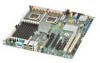
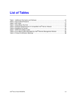
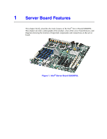
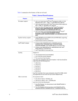
List of Figures Figure 1. Intel® Server Board S5000PSL 1 Figure 2. Server Board Connector and Component Locations 6 Figure 3. Configuration Jumpers 8 Figure 4. Back Panel Connectors and LEDs 12 Figure 5. DIMM Sockets...17 Figure 6. BIOS Bank Select Jumper in Force Lower Bank Position 25 Figure 7. Password Clear Jumper in Clear Password Position 26 Figure 8. CMOS Clr Jumper in the Clear CMOS Position 27 Figure 9. Locating DIMM Sockets 30 Figure 10. Installing FBDIMMs 31 Figure 11. Locating Processor Sockets 34 Figure 12. Opening Processor Socket Lever 35 Figure 13. Opening Load Plate 35 Figure 14. Removing Protective Cover from Load Plate 36 Figure 15. Setting Processor in Place 36 Figure 16. Installing Heatsink (passive heatsink shown 38 Figure 17. Locating Active Heatsink Cable Connections 39 Figure 18. Opening Processor Socket Lever 41 Figure 19. Opening Load Plate 41 Figure 20. Removing Processor from Socket 42 Figure 21. Installing Protective Cover onto Load Plate 42 Figure 22. Locating and Removing the CMOS Battery 44 Intel® Server Board S5000PSL xv

  • 1
  • 2
  • 3
  • 4
  • 5
  • 6
  • 7
  • 8
  • 9
  • 10
  • 11
  • 12
  • 13
  • 14
  • 15
  • 16
  • 17
  • 18
  • 19
  • 20
  • 21
  • 22
  • 23
  • 24
  • 25
  • 26
  • 27
  • 28
  • 29
  • 30
  • 31
  • 32
  • 33
  • 34
  • 35
  • 36
  • 37
  • 38
  • 39
  • 40
  • 41
  • 42
  • 43
  • 44
  • 45
  • 46
  • 47
  • 48
  • 49
  • 50
  • 51
  • 52
  • 53
  • 54
  • 55
  • 56
  • 57
  • 58
  • 59
  • 60
  • 61
  • 62
  • 63
  • 64
  • 65
  • 66
  • 67
  • 68
  • 69
  • 70
  • 71
  • 72
  • 73
  • 74
  • 75
  • 76
  • 77
  • 78
  • 79
  • 80
  • 81
  • 82
  • 83
  • 84
  • 85
  • 86
  • 87
  • 88
  • 89
  • 90

Intel
®
Server Board S5000PSL
xv
List of Figures
Figure 1. Intel
®
Server Board S5000PSL
..................................................................................
1
Figure 2. Server Board Connector and Component Locations
.................................................
6
Figure 3. Configuration Jumpers
...............................................................................................
8
Figure 4. Back Panel Connectors and LEDs
...........................................................................
12
Figure 5. DIMM Sockets
..........................................................................................................
17
Figure 6. BIOS Bank Select Jumper in Force Lower Bank Position
........................................
25
Figure 7. Password Clear Jumper in Clear Password Position
...............................................
26
Figure 8. CMOS Clr Jumper in the Clear CMOS Position
.......................................................
27
Figure 9. Locating DIMM Sockets
...........................................................................................
30
Figure 10. Installing FBDIMMs
................................................................................................
31
Figure 11. Locating Processor Sockets
...................................................................................
34
Figure 12. Opening Processor Socket Lever
..........................................................................
35
Figure 13. Opening Load Plate
...............................................................................................
35
Figure 14. Removing Protective Cover from Load Plate
.........................................................
36
Figure 15. Setting Processor in Place
.....................................................................................
36
Figure 16. Installing Heatsink (passive heatsink shown)
.........................................................
38
Figure 17. Locating Active Heatsink Cable Connections
........................................................
39
Figure 18. Opening Processor Socket Lever
..........................................................................
41
Figure 19. Opening Load Plate
...............................................................................................
41
Figure 20. Removing Processor from Socket
..........................................................................
42
Figure 21. Installing Protective Cover onto Load Plate
...........................................................
42
Figure 22. Locating and Removing the CMOS Battery
...........................................................
44