Intel S5000PSL User Guide - Page 24
Server Board Connector and Component Locations, SATA 5 or SAS 3 SAS 3 is - front panel connector
 |
UPC - 735858196055
View all Intel S5000PSL manuals
Add to My Manuals
Save this manual to your list of manuals |
Page 24 highlights
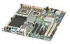
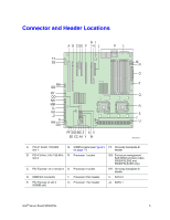
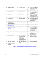
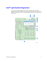
F. PCI Express x8 slot 5 G. PCI Express x8 slot 6 H. CMOS battery I. P12V4 connector J. RMM connector (connector for Intel® Remote Management Module) K. Back panel I/O ports (see Figure 4 on page 12) L. Diagnostic and Identify LEDs (see Figure 4 on page 12) M. System fan 6 header N. System fan 5 header O. Main power connector P. Auxiliary power signal connector V. System fan 4 header W. System fan 3 header X. IPMB connector Y. System fan 2 header Z. System fan 1 header AA. Processor power connector BB. USB header CC. IDE connector DD. Enclosure management SATA SGPIO header (product codes S5000SLSATA, S5000SLSATAR, S5000PSLROMB, and S5000PSLROMBR) EE. Intel® Local Control Panel header KK. SATA 2 or SAS 0 (SAS 0 is available only on product codes S5000PSLSAS and S5000PSLSASR) LL. SATA 3 or SAS 1 (SAS 1 is available only on product codes S5000PSLSAS and S5000PSLSASR) MM. SATA 4 or SAS 2 (SAS 2 is available only on product codes S5000PSLSAS, and S5000PSLSASR) NN. SATA 5 or SAS 3 (SAS 3 is available only on product codes S5000PSLSAS and S5000PSLSASR) OO. USB port PP. Front control panel header QQ. SATA_Key: SATA RAID 5 key connector (product codes S5000PSLSATA, S5000PSLSATAR, S5000PSLROMB, and S5000PSLROMBR only) RR. SAS_Key: SAS RAID 5 key connector (product codes S5000PSLSAS and S5000PSLSASR only) SS. Serial B / emergency management port header TT. Chassis intrusion header Figure 2. Server Board Connector and Component Locations 6 Intel® Server Board S5000PSL
-
 1
1 -
2
-
3
-
4
-
5
-
6
-
7
-
8
-
9
-
10
-
11
-
12
-
13
-
14
-
15
-
16
-
17
-
18
-
 19
19 -
 20
20 -
 21
21 -
 22
22 -
 23
23 -
 24
24 -
 25
25 -
 26
26 -
 27
27 -
 28
28 -
 29
29 -
30
-
31
-
32
-
33
-
34
-
35
-
36
-
37
-
38
-
39
-
40
-
41
-
42
-
43
-
44
-
45
-
46
-
47
-
48
-
49
-
50
-
51
-
52
-
53
-
54
-
55
-
56
-
57
-
58
-
59
-
60
-
61
-
62
-
63
-
64
-
65
-
66
-
67
-
68
-
69
-
70
-
71
-
72
-
73
-
74
-
75
-
76
-
77
-
78
-
79
-
80
-
81
-
82
-
83
-
84
-
85
-
86
-
87
-
88
-
89
-
90
 |
 |
