Intel S5000PSL User Guide - Page 49
Installing FBDIMMs
 |
UPC - 735858196055
View all Intel S5000PSL manuals
Add to My Manuals
Save this manual to your list of manuals |
Page 49 highlights
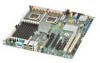
7. Make sure the clips at each end of the DIMM socket(s) are pushed outward to the open position. See letter "A" in Figure 10. 8. Holding the FBDIMM by the edges, remove it from its anti-static package. 9. Position the FBDIMM above the socket. Align the notch on the bottom edge of the FBDIMM with the key in the DIMM socket. The arrow for letter "B" in Figure 10 is pointing to the key in the socket. 10. Insert the bottom edge of the FBDIMM into the socket. 11. When the FBDIMM is inserted, push down on the top edge of the FBDIMM until the retaining clips snap into place. See letter "C" in Figure 10. 12. Make sure the clips latch firmly in place. See letter "D" in Figure 10. C D B A TP000425 Figure 10. Installing FBDIMMs 13. Reinstall and reconnect any parts you removed or disconnected to reach the DIMM sockets. See the documentation that came with your chassis for instructions on removing chassis components. 14. Replace the chassis cover and reconnect the AC power cord. See the documentation that came with your chassis for instructions on installing the chassis cover. Intel® Server Board S5000PSL 31
-
 1
1 -
2
-
3
-
4
-
5
-
6
-
7
-
8
-
9
-
10
-
11
-
12
-
13
-
14
-
15
-
16
-
17
-
18
-
19
-
20
-
21
-
22
-
23
-
24
-
25
-
26
-
27
-
28
-
29
-
30
-
31
-
32
-
33
-
34
-
35
-
36
-
37
-
38
-
39
-
40
-
41
-
42
-
43
-
 44
44 -
 45
45 -
 46
46 -
 47
47 -
 48
48 -
 49
49 -
 50
50 -
 51
51 -
 52
52 -
 53
53 -
 54
54 -
55
-
56
-
57
-
58
-
59
-
60
-
61
-
62
-
63
-
64
-
65
-
66
-
67
-
68
-
69
-
70
-
71
-
72
-
73
-
74
-
75
-
76
-
77
-
78
-
79
-
80
-
81
-
82
-
83
-
84
-
85
-
86
-
87
-
88
-
89
-
90
 |
 |
