JVC TK-C1460U Instruction Manual
JVC TK-C1460U - 1/3-in Ccd Wide Range Dsp Color Camera Manual
 |
View all JVC TK-C1460U manuals
Add to My Manuals
Save this manual to your list of manuals |
JVC TK-C1460U manual content summary:
- JVC TK-C1460U | Instruction Manual - Page 1
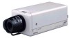
COLOUR VIDEO CAMERA TK-C1460 INSTRUCTIONS BF LOOK DIGITAL COLOR VIDEO CAMERA For Customer Use: Enter below the Serial No. which is located on the body. Retain this information for future reference. Model No. TK-C1460 Serial No. SC961012H-001 (CD-ROM) E-1 - JVC TK-C1460U | Instruction Manual - Page 2
to your home, consult your dealer or local power company. For appliance designed to operate from battery power, refer to the operating instructions. 10. This appliance system is equipped with a 3-wire grounding type plug (a plug having a third (grounding) pin). This plug will only fit into - JVC TK-C1460U | Instruction Manual - Page 3
service personnel under the following conditions: a. When the power cord or plug is damaged or frayed. b. If liquid has been spilled into the appliance. c. If the appliance has been exposed to rain or water. d. If the appliance does not operate normally by following the operating instructions - JVC TK-C1460U | Instruction Manual - Page 4
to the presence of important operating and maintenance (servicing) instructions in the literature accompanying the appliance. Information for USA approved by JVC could void the user's authority to operate the equipment. Due to design modifications, data given in this instruction book are subject - JVC TK-C1460U | Instruction Manual - Page 5
These instrustions are for TK-C1460U and TK-C1460E) Before beginning to operate this unit, please read the instruction manual carefully in order to ...14 Mounting the lens ...15 Connections on the back 16 Mounting the camera ...18 Lens adjustment ...20 Back focus adjustment ...21 Auto white balance - JVC TK-C1460U | Instruction Manual - Page 6
impossible to record due to a problem in the video camera, VCR or video tape. Ⅲ We do not accept liability for any damage to the camera in cases when it is dropped because of incomplete installation due to not observing the installation instructions correctly. Please be careful when installing - JVC TK-C1460U | Instruction Manual - Page 7
be sure to use a housing and the like. ● Do not install or use the camera in the following places. • In a place exposed to rain or moisture. • In tissue) which has been soaked in a solution of water and a neutral detergent. ● TK-C1460U and TK-C1460E The unit is to be powered by a DC 12 V or an AC 24 - JVC TK-C1460U | Instruction Manual - Page 8
the locking screw 3 again. 3 [BF LOCK] Back focus locking screw This serves to fix the back focus-adjusting ring. 4 Camera-mounting bracket The bracket has been attached on the bottom of the camera before shipment. It can also be attached on the top according to the circumstance. To re-attach the - JVC TK-C1460U | Instruction Manual - Page 9
! @# $ SET AWC MENU CAMERA SETUP EXT TERM-OFF INT/GL DUPLEX RX TERM-OFF NOT USED ON LL DC: In case of lens without EE amp built-in. ( ) At time of factory shipment VIDEO: TK-C1460E DC: TK-C1460U 10 [IRIS] Iris Terminal This is connected to an automatic iris control lens. (੬ Page 15) 11 [MENU - JVC TK-C1460U | Instruction Manual - Page 10
and adjusting the vertical phase can reduce the monitor sync disturbances occurring when the camera image is switched. (This cannot be used in regions where the power frequency is 60 Hz (50 Hz) ( ):TK-C1460U) (INT/GL: At time of factory shipment) 16 [DUPLEX, SIMPLEX] Selector Switch for Transmission - JVC TK-C1460U | Instruction Manual - Page 11
RX+ RX- AUX GND A B C D SYNC IN VIDEO OUT POWER Y/C OUT SEE INSTRUCTION MANUAL ¤ ‹ 19 [DC 12V, AC 24V] Power input terminals To input DC 12V or AC Power indicator lamp This lamp lights when power is supplied to the camera. 25 [SYNC IN] Sync signal input connector This BNC connector accepts - JVC TK-C1460U | Instruction Manual - Page 12
OFF (switch) Av Pk L H ALC LEVEL Camera TK-C1460 Camera TK-C1460 Control signal cable Video signal cable Power cable AC24V or DC12V Camera 2 MACHINE ID:2 (Menu screen) RX TERM: OFF (switch) Camera TK-C1460 AC24V or DC12V Av Pk L H ALC LEVEL Camera 8 MACHINE ID:8 (Menu screen) RX TERM: ON - JVC TK-C1460U | Instruction Manual - Page 13
Set this item to match the RM-P2580 VIDEO INPUT terminal number for each camera. When connecting ● Turn OFF the power supply to all equipment to be used before making connections. ● Carefully read the Instructions for each piece of equipment to be used before making connections. ● For the - JVC TK-C1460U | Instruction Manual - Page 14
(੬ Page 10) 6.Back focus adjustment (੬ Page 21) Av Pk L H ALC LEVEL SET MENU CAMERA SETUP EXT TERM-OFF INT/GL DUPLEX RX TERM-OFF IOT USED ON LL SIMPLEX ON VIDEO DC AUX GND A B C D SYNC IN VIDEO OUT POWER Y/C OUT SEE INSTRUCTION MANUAL To alarm terminals such as switches Monitor E-14 - JVC TK-C1460U | Instruction Manual - Page 15
such will not allow normal installation and damage the inner part of the camera, resulting in a malfunction. Lens Flange back (c) Dimension (b) C mount F mark indicates a focal point. 13 2. Mount the lens on the camera by turning the lens clockwise. Adjust its position. 24 3. When using an - JVC TK-C1460U | Instruction Manual - Page 16
A B C D SYNC IN VIDEO OUT POWER Y/C OUT SEE INSTRUCTION MANUAL Maximum extension (reference) 100 m 260 m 410 m 500 m drop at the camera side to below 10%, or place the power supply near to the camera. If voltage drop TK-C1460U Class 2 only TK-C1460E Isolated power supply only E-16 - JVC TK-C1460U | Instruction Manual - Page 17
Control signal cables These cables should be connected only when it is required to control the camera using the RS-442A or RS-485 signals. The use of 0.65 4-conductor twisted containing too much jitter, such as a VCR or videodisc playback signal. • For details, consult a JVC authorized dealer. E-17 - JVC TK-C1460U | Instruction Manual - Page 18
. 7mm Rotation prevention hole Furthermore, make use of the rotation prevention hole to prevent the camera from falling and securely mount the camera. Special precautions must be taken for mounting the camera on a wall or a ceiling. We are not liable for any damage caused by improper installation - JVC TK-C1460U | Instruction Manual - Page 19
Fixing unit or Pan/Tilt unit. • Mounting from the top Remove the CAMERA MOUNTING BRACKET from the bottom of the camera by removing two fixing screws as shown w. Attach the CAMERA MOUNTING BRACKET to the top, then mount the camera on the Fixing Unit as shown e. Make sure that two original screws are - JVC TK-C1460U | Instruction Manual - Page 20
, and check the image. The camera has been factory-adjusted to the best position, but it may need to be adjusted according to the object conditions or combination of lenses. If the image is unnatural, adjust it as follows: (Also read the instruction manual of the lens.) LEVEL adjustment • LEVEL - JVC TK-C1460U | Instruction Manual - Page 21
screw by turning it clockwise ( ). • With a zoom lens If the image is out of focus when zooming (telephoto wide-angle), adjust the camera as follows: 1. Loosen the back focus locking screw by turning it counterclocckwise ( ) with a screwdriver. 2. Shoot a comparatively dark scene with thin lines - JVC TK-C1460U | Instruction Manual - Page 22
a white object under the same lighting condition as the object to be shot and zoom in to fill the screen with white. SET AWC MENU CAMERA SETUP EXT TERM-OFF INT/GL DUPLEX RX TERM-OFF NOT USED ON LL SIMPLEX ON IRIS VIDEO DC 2. When the AWC button is pressed - JVC TK-C1460U | Instruction Manual - Page 23
item. A L C SET T I NGS I R I S LEVEL AV ERAGE : P EAK SHUT T ER ( E x DR ) AGC MODE SENSE UP PR I OR I T Y BLC NORMAL 8: 2 NORMAL 2 0 dB OF F --- OF F SET MENU CAMERA SETUP EXT TERM-OFF INT/GL DUPLEX RX TERM-OFF NOT USED ON LL SIMPLEX ON IRIS VIDEO DC 1. Press the MENU button. The MENU - JVC TK-C1460U | Instruction Manual - Page 24
੬ Page 35 F ACTORY SE T T I NGS CAN CE L CL E AR (W I T HOUT T I T L E ) CL E AR ( AL L ) D AT A CL EARE D The word "COLOUR" is displayed as "COLOR" on the TK-C1460U. E-24 - JVC TK-C1460U | Instruction Manual - Page 25
PR I OR I T Y --- BLC OF F B&W/COLOUR MODE ੬ Page 32 MODE S EL E C T CAMERA T I T L E ED I T . . RE V ERS E MODE OF F AL M . T MN O P QRS T U VWX Y Z a b c d e f g h i j k l mn o p q r s t uvwxy z WIDE TELE T i t l e Di s l ay (The TK-C1460U does not display these characters.) E-25 - JVC TK-C1460U | Instruction Manual - Page 26
values Initial value V PHASE This adjusts the vertical synchronization to those of other cameras 0 when a selector switch for the synchronizing system on the side is at LL. (50Hz (60Hz) power region only. ( ): TK-C1460U) When it is not set to LL, "---" will appear, disabling change the set - JVC TK-C1460U | Instruction Manual - Page 27
picture shot at 1/100 (1/120) sec. shutter speed with a picture shot by a high-speed shutter. ( ): TK-C1460U NORMAL: This fixes the shutter speed to 1/50 (1/60). The ExDR does not function. MANUAL: This sets the shutter speed by the item SHUTTER SPEED on the SHUTTER screen. The ExDR does not - JVC TK-C1460U | Instruction Manual - Page 28
according to the brightness of a subject. When using M.ExDR, be sure to set M.ExDR SPEED in advance. When the SHUTTER (ExDR) item is set to MANUAL or AUTO, "- - -" appears, disabling setting. To give priority to the low-brightness par ts of the subject... increase the value To give priority to the - JVC TK-C1460U | Instruction Manual - Page 29
four types. (Indicated positions on the screen are rough guides. Execute required settings after checking and confirming the functions 3 AREA 4 * The indicated position on the screen should be used as a rough guide. EDIT 1 to EDIT 2: When the SET button is pressed, the user light metering areas - JVC TK-C1460U | Instruction Manual - Page 30
. (੬ Page 33.) AUX LEVEL When the "B&W" function is set to "AUTO", this function sets the signal level of the object at which the camera will automatically switch to B&W mode. LOW : Switches to B&W mode when the signal level of the object indicates low illumination. NORMAL: Switches to B&W mode - JVC TK-C1460U | Instruction Manual - Page 31
Item Functions and set values Initial value WHITE BALANCE Selects the white balance adjustment function. The white balance can be adjusted manually or automatically for light within the colour temperature range of 2500K to 8000K. • ATW: Auto-Tracking White Balance mode. This automatically - JVC TK-C1460U | Instruction Manual - Page 32
MENU SETTING MODE SELECT Screen Titles, image reversion, etc., are set. Item Functions and set values CAMERA TITLE EDIT Bring up the CAMERA TITLE, EDIT screen. (੬ Page 38) Initial value - REVERSE MODE ALM.TITLE SIZE Settings are executed for image reversion. OFF: Image does not reverse. - JVC TK-C1460U | Instruction Manual - Page 33
IN) MOTION: A signal is output if there is a change in the area set on the MOTION DETECT screen. B&W OUT: A signal is output when the camera switches to B&W or Colour mode. B&W IN: Set to this position when inputting the B&W/ Colour switching control signal to the AUX terminal. (੬ Page 11, 30 - JVC TK-C1460U | Instruction Manual - Page 34
MENU SETTING MOTION DETECT Screen Settings are executed about the motion detecting function that emits alarm signals when there exists any motion in the image. Alarm signals are output from the auxiliary terminals on the back. Item Functions and set values Initial value MODE This sets ON/OFF - JVC TK-C1460U | Instruction Manual - Page 35
. P TO P MACHINE ID This is set when the STYLE item is set to M.DROP. This is the number that identifies individual cameras in a group. No proper function can be realized if an ID number is repeated within a system. A combined use with the RM-P2580 necessitates the setting - JVC TK-C1460U | Instruction Manual - Page 36
I OR I T Y BLC NORMAL 8: 2 NORMAL 2 0 dB OF F MOT I ON EDIT 1 SET AWC MENU CAMERA SETUP EDIT 1 screen SET button EDIT 2 screen SET button 1. Set the item BLC on the ALC Light metering SETTING screen used as a rough guide. E-36 * To use the set metering area, set the item BLC to EDIT1 or - JVC TK-C1460U | Instruction Manual - Page 37
Balance When automatic adjustment of the white balance results in a "reddish screen", etc., adjust the white balance manually. MENU button SET button SET AWC MENU CAMERA SETUP V I DE O ADJ U ST WH I T E BAL ANCE COLOUR L EVE L E NHANCE "COLOUR" is displayed as "COLOR" on the TK-C1460U. E-37 - JVC TK-C1460U | Instruction Manual - Page 38
returns to MODE SELECT. C AME R A T I T L E 0 12 3 4 5 6 78 9 - : / . , AB C DE FG H I J K L MN O P QRS T U VWX Y Z a b c d e f g h i j k l mn o p q r s t uvwxy z v WI DE TE LE T i t l e Di s l ay CAMERA TITLE screen Title input area (The TK-C1460U does not display these characters.) E-38 - JVC TK-C1460U | Instruction Manual - Page 39
. 6. Upon completion of setting, press the MENU button. The screen returns to the MOTION DETECT menu. MEMO • Indicated positions on the screen are rough guides. Be sure to check and conform the positions on the actual screen. * It is possible to check and confirm the set areas on the DEMONSTRATION - JVC TK-C1460U | Instruction Manual - Page 40
the AUX terminal on the back of this unit. MENU button SET button SET AWC MENU CAMERA SETUP B&W/COLOUR MODE B&W LEVE L AUX N O RMA L MODE S EL E C T CAMERA T I T L E ED I T . . RE V ERS E MODE OF F AL M . T I T LE S I Z E DOUBLE AL ARM COLOUR WH I T E AUX TERMINAL B&W OUT D. ZOOM - JVC TK-C1460U | Instruction Manual - Page 41
+ TX- RX+ RX- AUX GND A B C D SYNC IN VIDEO OUT POWER Y/C OUT SEE INSTRUCTION MANUAL B&W: Make signal COLOR: Break signal Sensor or switch Outside control device TK-C1460 It is requested that you consult our JVC dealer about connecting devices, etc. Ⅲ Set the B&W item to AUX. MENU button - JVC TK-C1460U | Instruction Manual - Page 42
galvanometnc-iris lens) Wind twice Av Pk L H ALC LEVEL IRIS VIDEO DC Ferrite core Notes: Install the ferrite cores within 50 mm of the camera-side connectors. (Fasten the ferrite core with the wire clamp provided.) For lens connection: Pass the lens cable through the ferrite core twice and - JVC TK-C1460U | Instruction Manual - Page 43
: -10°C to 50°C (operation) 0°C to 40°C (recommended) Mass: 640 ˝ Accessory: TK-C1460U Instructions 1 Ferrite core 1 4P plug 1 Warranty card 1 Service Information card ......... 1 TK-C1460E Instructions 2 Ferrite core 1 4P plug 1 Design and specifications are subject to change - JVC TK-C1460U | Instruction Manual - Page 44
TK-C1460 COLOUR VIDEO CAMERA VICTOR COMPANY OF JAPAN, LIMITED ® is a registered trademark owned by VICTOR COMPANY OF JAPAN, LTD. ® is a registered trademark in Japan, the U.S.A., the U.K. and many other countries. © 2001 VICTOR COMPANY OF JAPAN, LIMITED Printed in Thailand SC961011H-001 - JVC TK-C1460U | Instruction Manual - Page 45
FARBVIDEOKAMERA TK-C1460 BEDIENUNGSANLEITUNG BF LOOK DIGITAL COLOR VIDEO CAMERA SC961012H-001 (CD-ROM) - JVC TK-C1460U | Instruction Manual - Page 46
Safety Precautions Due to design modifications, data given in this instruction book are subject to possible change without prior notice. WARNING: TO REDUCE THE RISK OF FIRE OR ELECTRIC SHOCK, DO NOT EXPOSE THIS APPLIANCE TO RAIN OR MOISTURE. G-2 - JVC TK-C1460U | Instruction Manual - Page 47
für den Kauf unseres Erzeugnisses. (Diese Anleitung gilt für das Modell TK-C1460U und TK-C1460E.) Bitte lesen Sie diese Bedienungsanleitung vor der Verwendung des Ger 34 Manuelle Einstellung des Weissableichs 35 Einstellung CAMERA TITLE 36 Einstellung der Bewegungsentdeckungsfunktion 37 Ausgabe - JVC TK-C1460U | Instruction Manual - Page 48
dass normale Aufzeichnung möglich ist. Ⅲ Wir akzeptieren keinerlei Haftung für den Verlust einer Aufzeichnung, falls eine Aufzeichnung wegen eines Problems der Videokamera, des Videorekorders oder des Videobandes unmöglich sein sollte. Ⅲ Wir akzeptieren keinerlei Haftung für Beschädigung der Kamera - JVC TK-C1460U | Instruction Manual - Page 49
verschmutzten Teile mit einem Lappen oder einem Papiertaschentuch, angefeuchtet mit einer Lösung von Wasser und einem neutralen Waschmittel. ● TK-C1460U und TK-C1460E Das Gerät wird durch eine Stromversorgung mit 12 V Gleichspannung oder 24 V Wechselspannung angetrieben. Die Stromversorgung mit 24 - JVC TK-C1460U | Instruction Manual - Page 50
EINLEITUNG Bedienungselemente, Anschlüsse und Anzeigen 2 1 3 4 5 7 6 1 Objektivfassung Die Objektivfassung ist mit kompatibel mit Objektiven mit C-Fassung und mit CS-Fassung. 2 Einstellring für die Schnittweite Dieser Ring ermöglicht Einstellung der Schnittweite und Umschalten der - JVC TK-C1460U | Instruction Manual - Page 51
sse und Anzeigen (fortgesetzt) ! @# $ SET AWC MENU CAMERA SETUP EXT TERM-OFF INT/GL DUPLEX RX TERM-OFF NOT ein Objektiv ohne eingebauten EE-Verstärker ( ) Werkseinstellung VIDEO: TK-C1460E DC: TK-C1460U 10 [IRIS] Blendenanschluss Hier wird ein Objektiv mit automatischer Blendensteuerung - JVC TK-C1460U | Instruction Manual - Page 52
Umschalten des Kamerabildes verringern. (Diese Funktion kann nicht in Bereichen verwendet werden, in denen die Netzfrequenz 60 Hz (50 Hz) ( ): TK-C1460U ist.) (INT/GL: Werkseinstellung) 16 [DUPLEX, SIMPLEX] Wahlschalter für das Übertragungssystem Wenn die Einstellung geändert worden ist, so schalten - JVC TK-C1460U | Instruction Manual - Page 53
AC24V CLASS 2 ONLY(U TYPE) ISOLATED POWER ONLY (E TYPE) fi › TX+ TX- RX+ RX- AUX GND A B C D SYNC IN VIDEO OUT POWER Y/C OUT SEE INSTRUCTION MANUAL ¤ ‹ 19 [DC 12 V, AC 24 V] Stromversorgungsanschlüsse Für Versorgung mit 12 V Gleichspannung oder 24 V Wechselspannung. 20 [TX+A, TX-B, RX+C, RX - JVC TK-C1460U | Instruction Manual - Page 54
Schalter) Av Pk L H ALC LEVEL Kamera TK-C1460 Kamera TK-C1460 Steuersignalkabel Videosignalkabel Netzkabel 12 V Gleichspannung oder 24 CAMERA (Kamera) SW (Schalter) COM (Kommunikation) TO CAMERA (Zur Kamera) Fernsteuerung RM-P2580 POWER TO CAMERA RX+ RX- TX+ TX- DATA I / O UNIT CAMERA COM - JVC TK-C1460U | Instruction Manual - Page 55
und an RMP2580 erleichtern korrekten Anschluss. TX B RX+ C Verbinden Sie Anschlüsse mit der gleichen Markierung. RX D Ⅲ Einstellen der Schalter (੬ Seite 8) SET AWC MENU CAMERA SETUP EXT TERM-OFF INT/GL DUPLEX RX TERM-OFF NOT USED ON LL SIMPLEX ON VIDEO IRIS DC EXT TERM-OFF INT/GL DUPLEX - JVC TK-C1460U | Instruction Manual - Page 56
Seite 8) 6.Schnittweiteneinstellung (੬ Seite 19) Av Pk L H ALC LEVEL SET MENU CAMERA SETUP EXT TERM-OFF INT/GL DUPLEX RX TERM-OFF IOT USED ON LL SIMPLEX TX+ TX- RX+ RX- AUX GND A B C D SYNC IN VIDEO OUT POWER Y/C OUT SEE INSTRUCTION MANUAL Zu Alarmklemmen, z.B. Schaltern Monitor G-12 - JVC TK-C1460U | Instruction Manual - Page 57
Anbringen des Objektivs Bringen Sie das Objektiv entsprechend der nachfolgend beschriebenen Verfahren an. BF LOCK (b) F (c) 3. VIDEO DC 1. Überprüfen Sie vor dem Anschluss eines Objektivs, ob es eine C- oder eine CSFassung hat. Wenn Sie die Anbringungsmethode ändern wollen, so lösen Sie die - JVC TK-C1460U | Instruction Manual - Page 58
TX- RX+ RX- AUX GND A B C D SYNC IN VIDEO OUT POWER Y/C OUT SEE INSTRUCTION MANUAL Schließen Sie die Stromversorgung für 12 V Gleichspannung oder 24 V Wechselspannung an die Anschlüsse DC sollte den folgenden Punkten entsprechen: TK-C1460U: Nur Klasse 2 TK-C1460E: Nur isolierte Stromversorgung - JVC TK-C1460U | Instruction Manual - Page 59
+ TX- RX+ RX- AUX GND A B C D SYNC IN VIDEO OUT POWER Y/C OUT SEE INSTRUCTION MANUAL Ⅲ Steuersignalkabel Diese Kabel sollten nur angeschlossen werden, wenn es erforderlich ist, die Kamera mit RS-422A oder RS . • Wenden Sie sich für Einzelheiten bitte an einen autorisierten JVC-Händler. G-15 - JVC TK-C1460U | Instruction Manual - Page 60
ANSCHLUSS/INSTALLATION Anbringen der Kamera Stativgewinde Kamerahalterung Verwenden Sie zum Anbringen der Kamera auf einer Befestigungseinheit, einem Schwenkkopf usw. das Stativgewinde an der Kamerahalterung. ACHTUNG: Verwenden Sie eine Schraube mit einer Länge von weniger als 7 mm von - JVC TK-C1460U | Instruction Manual - Page 61
Anbringen der Kamera (fortgesetzt) q Installation der Kamera • Diese Kamera ist ursprünglich für Anbringung von der Unterseite her entworfen, wie in q gezeigt. Das IRIS VIDEO DC Gewindeloch ist ein Standardstativgewinde (1/4-20 UNC). Beispiel: Befestigungseinheit oder Kameraschwenkkopf. • - JVC TK-C1460U | Instruction Manual - Page 62
ANSCHLUSS/INSTALLATION Einstellen des Objektivs Schließen Sie die Kamera entsprechend der Anschlussmethode an, schalten Sie sie ein, zeigen Sie ein Bild auf dem Monitor an und überprüfen Sie das Bild. Die Kamera ist im Werk auf die beste Position eingestellt worden, aber abhängig von den - JVC TK-C1460U | Instruction Manual - Page 63
Einstellen der Schnittweite Ⅲ Einstellen der Schnittweite Achten Sie darauf, die Schnittweite einzustellen, wenn Sie die Anbringungsmethode für das Objektiv ändern oder ein anderes Objektiv verwenden.: • Verwenden Sie für genaue Einstellung der Schnittweite den elektronischen Verschluss und das ND- - JVC TK-C1460U | Instruction Manual - Page 64
. Wenn die Hauptlichtquelle geändert wird, sollte deshalb der Weißabgleich durch Drücken der Taste AWC neu eingestellt werden. Taste AWC SET AWC MENU CAMERA SETUP EXT TERM-OFF INT/GL DUPLEX RX TERM-OFF NOT USED ON LL SIMPLEX ON IRIS VIDEO DC AWC OPERATION AWC OK Während des - JVC TK-C1460U | Instruction Manual - Page 65
zu stellen. A L C SET T I NGS I R I S LEVEL AV ERAGE : P EAK SHUT T ER ( E x DR ) AGC MODE SENSE UP PR I OR I T Y BLC NORMAL 8: 2 NORMAL 2 0 dB OF F --- OF F SET MENU CAMERA SETUP EXT TERM-OFF INT/GL DUPLEX RX TERM-OFF NOT USED ON LL SIMPLEX ON IRIS VIDEO DC 1. Drücken Sie die Taste MENU - JVC TK-C1460U | Instruction Manual - Page 66
NORMAL 10s ੬ Seite 37 ੬ Seite 33 F ACTORY SE T T I NGS CAN CE L CL E AR (W I T HOUT T I T L E ) CL E AR ( AL L ) D AT A CL EARE D Das Wort „COLOUR" wird am TK-C1460U als „COLOR" angezeigt. G-22 - JVC TK-C1460U | Instruction Manual - Page 67
PR I OR I T Y --- BLC OF F B&W/COLOUR MODE ੬ Seite 30 MODE S EL E C T CAMERA T I T L E ED I T . . RE V ERS E MODE OF F AL M . T I K L MN O P QRS T U VWX Y Z a b c d e f g h i j k l mn o p q r s t uvwxy z WIDE TELE T i t l e Di s l ay (TK-C1460U zeigt diese Zeichen nicht an.) G-23 - JVC TK-C1460U | Instruction Manual - Page 68
dieser Schalter nicht auf LL gestellt ist, wird "- - -" angezeigt und der Einstellwert kann nicht geändert werden. TK-C1460U [Einstellwert: -131 bis 0 bis 131] TK-C1460E [Einstellwert: -156 bis 0 bis 156] H PHASE Hiermit wird die horizontale Synchronisation auf die einer 0 anderen Kamera - JVC TK-C1460U | Instruction Manual - Page 69
) sec aufgenommenen Bildes mit einem mit einer kurzen Verschlusszeit aufgenommenen Bild. ( ): TK-C1460U NORMAL: Hierbei ist die Verschlusszeit auf 1/50 (1/60) sec fixiert. Die Funktion ExDR ist nicht wirksam. MANUAL: Hierbei wird die Verschlusszeit entsprechend dem Punkt SHUTTER SPEED am Bildschirm - JVC TK-C1460U | Instruction Manual - Page 70
32-fachen Wert erhöht. Mit zunehmender Empfindlichkeit wird die Verschlusszeit länger, was in unnatürlicher Bewegung resultiert. Wenn SHUTTER (ExDR) auf MANUAL oder M.ExDR eingestellt ist, erscheint "- - -" und die Funktion SENSE UP ist unwirksam. [Einstellwerte: OFF, X2 AUTO, X4 AUTO, X8 AUTO, X16 - JVC TK-C1460U | Instruction Manual - Page 71
Punkt PRIORITY BLC Funktionen und Einstellwerte Ausgangswert Dieser Punkt stellt die Reihenfolge ein, in der AGC abnimmt und die Verschlusszeit länger wird, wenn die Helligkeit des Objekts abnimmt. Wenn der Punkt AGC MODE oder der Punkt SENSE UP auf OFF gestellt ist, wird "- - -" angezeigt und - JVC TK-C1460U | Instruction Manual - Page 72
Menüeinstellung Bildschirm ALC SETTING (ALC-Einstellung) (fortgesetzt) Punkt Funktionen und Einstellwerte Ausgangswert B&W COLOUR Diese Funktion stellt den Farbmodus auf Farbe oder MODE ..... Schwarzweiß. Beim Umschalten des Modus zwischen Farbe (COLOUR) und Schwarzweiß (B&W) kann die - JVC TK-C1460U | Instruction Manual - Page 73
Bildschirm VIDEO ADJUST Einstellungen für Videosignale werden durchgeführt. Punkt WHITE BALANCE COLOUR LEVEL ENHANCE LEVEL PEDESTAL LEVEL AUTO BLACK CTL Funktionen und Einstellwerte Ausgangswert Wahl der Einstellungsfunktion für den Weissabgleich. Der Weissabgleich kann für Licht im - JVC TK-C1460U | Instruction Manual - Page 74
Bildschirm MODE SELECT Titel, Bildumkehrungen usw. werden eingestellt. Punkt CAMERA TITLE EDIT Funktionen und Einstellwerte Zeigen Sie den Bildschirm CAMERA TITLE; EDIT an. (੬ Seite 36) Ausgangswert - REVERSE MODE ALM.TITLE SIZE Einstellungen für Bildumkehr. OFF: Das Bild wird nicht umgekehrt. - JVC TK-C1460U | Instruction Manual - Page 75
Punkt AUX TERMINAL D-ZOOM MAX Funktionen und Einstellwerte Ausgangswert Zum Einstellen des Signalein- oder -ausgangs am Anschluss AUX. MOTION : Bei einer Änderung in dem am Bildschirm MOTION DETECT (Bewegungsentdeckung) eingestellten Bereich wird ein Signal ausgegeben. B&W OUT : Beim - JVC TK-C1460U | Instruction Manual - Page 76
Menüeinstellung Bildschirm MOTION DETECT Einstellungen für die Bewegungsentdeckungsfunktion, bei der Alarmsignale abgegeben werden, wenn eine Bewegung im Bild vorhanden ist. Alarmsignale werden von den Hilfsklemmen an der Rückseite ausgegeben. Punkt MODE LEVEL AREA EDIT ALARM TIME DEMONSTRATION - JVC TK-C1460U | Instruction Manual - Page 77
Bildschirm COMMUNICATION Einstellungen für die Anschlüsse für Steuersignale an der Rückseite. Wenn die Einstellung geändert wird, so achten Sie unbedingt darauf, die Stromversorgung aus- und wieder einzuschalten. Punkt STYLE MACHINE ID Funktionen und Einstellwerte Ausgangswert Einstellung eines - JVC TK-C1460U | Instruction Manual - Page 78
T ER ( E x DR ) AGC MODE SENSE UP PR I OR I T Y BLC NORMAL 8: 2 NORMAL 2 0 dB OF F MOT I ON EDIT 1 Taste MENU Taste SET SET AWC MENU CAMERA SETUP Bildschirm EDIT 1 Taste SET Bildschirm EDIT 2 Taste SET Lichtmess bereich 1. Stellen Sie den Punkt BLC am Bildschirm ALC SETTING auf EDT1. 2. Dr - JVC TK-C1460U | Instruction Manual - Page 79
zu einem „rötlichen Bildschirm" usw. führt, so stellen Sie den Weissabgleich manuell ein. Taste MENU Taste SET SET AWC MENU CAMERA SETUP V I DE O ADJ U ST WH I T E BAL ANCE COLOUR L EVE L E NHANCE L E V BALANCE CONTROL Das Wort „COLOUR" wird am TK-C1460U als „COLOR" angezeigt. G-35 - JVC TK-C1460U | Instruction Manual - Page 80
K L MN O P QRS T U VWX Y Z a b c d e f g h i j k l mn o p q r s t uvwxy z w WI DE TE LE T i t l e Di s l ay Bildschirm CAMERA TITLE Titeleingabebereich (TK-C1460U zeigt diese Zeichen nicht an.) 1. Wählen Sie den Punkt CAMERA TITLE am Bildschirm MODE SELECT und drücken Sie die Taste SET. Der - JVC TK-C1460U | Instruction Manual - Page 81
Einstellung der Bewegungsentdeckungsfunktion Der Funktionsbereich für die Bewegungsentdeckung (MOTION DETECT) kann frei eingestellt werden. MOT I O N DE T EC T M ODE L E VE L AREA E D I T . . AL ARM T I ME DEMON S TRA T I ON . . OFF NORMAL 10s Bildschirm MOTION DETECT Blinkt - JVC TK-C1460U | Instruction Manual - Page 82
des Gerätes auszugeben. Machen Sie die folgenden Einstellungen. Taste MENU Taste SET SET AWC MENU CAMERA SETUP B&W/COLOUR MODE B&W LEVE L AUX N O RMA L MODE S EL E C T CAMERA T I T L E ED I T . . RE V ERS E MODE OF F AL M . T I T LE S I Z E DOUBLE AL ARM COLOUR WH I T E AUX TERMINAL - JVC TK-C1460U | Instruction Manual - Page 83
IN VIDEO OUT POWER SEE INSTRUCTION MANUAL Externe Steuerung TK-C1460 Für den Anschluss von Ger äten usw. sollten Sie sich an Ihren JVCHändler wenden. Ⅲ Stellen Sie den Punkt B&W auf Taste MENU Taste SET AUX. SET AWC MENU CAMERA - JVC TK-C1460U | Instruction Manual - Page 84
SONSTIGES Ferritkerninstallation Verwenden Sie die mitgelieferten Ferritkerne beim Anschluss des Objektivs bzw. beim Anschluss an die Stromversorgung, um elektromagnetische Kompatibilität beizubehalten. Objektiv mit Videoblende (oder Objektiv mit galvanometrischer Blende) Zwei Windungen Av Pk L H - JVC TK-C1460U | Instruction Manual - Page 85
) Kommunikation: RS-422A oder RS-485 (umschaltbar) 9600 bit/s Objektivfassung: C-/CS-Fassung Stromversorgung und Stromverbrauch: TK-C1460U 24 V Wechselspannung ` , 60 Hz, DC12V 6,0W TK-C1460E 24 V Wechselspannung `, 50 Hz/60 Hz, 12 V Gleichstrom 550 mA Umgebungstemperatur: -10°C bis 50 - JVC TK-C1460U | Instruction Manual - Page 86
TK-C1460 VICTOR COMPANY OF JAPAN, LIMITED ® is a registered trademark owned by VICTOR COMPANY OF JAPAN, LTD. ® is a registered trademark in Japan, the U.S.A., the U.K. and many other countries. © 2001 VICTOR COMPANY OF JAPAN, LIMITED Printed in Thailand SC961012H-001 - JVC TK-C1460U | Instruction Manual - Page 87
CAMERA VIDEO COULEUR TK-C1460 MANUEL D'INSTRUCTIONS BF LOOK DIGITAL COLOR VIDEO CAMERA SC961012H-001 (CD-ROM) - JVC TK-C1460U | Instruction Manual - Page 88
Safety Precautions Due to design modifications, data given in this instruction book are subject to possible change without prior notice. WARNING: TO REDUCE THE RISK OF FIRE OR ELECTRIC SHOCK, DO NOT EXPOSE THIS APPLIANCE TO RAIN OR MOISTURE. F-2 - JVC TK-C1460U | Instruction Manual - Page 89
(Ces instructions s'appliquent au modèle TK-C1460U, TK-C1460E.) Avant de mettre l'appareil en service, veuillez lire attentivement toutes ces instructions de ...34 Réglage manuel de la balance des blancs 35 Réglage de CAMERA TITLE 36 Réglage de la fonction MOTION DETECT 37 Envoi du signal - JVC TK-C1460U | Instruction Manual - Page 90
Nous déclinons toute responsabilité pour les dommages de la caméra résultant d'une chute due à une installation incomplète suite au non respect des instructions d'installation. Faire attention lors de l'installation de la caméra. Ⅲ La fonction de détecteur de mouvement n'est pas conçue pour empêcher - JVC TK-C1460U | Instruction Manual - Page 91
de l'entretien de la caméra. • Ce manuel d'instructions a été préparé en quatre langues (allemand, fran trempé dans une solution de détergent naturel. ● TK-C1460U et TK-C1460E L'appareil doit être alimenté sur un courant gain lorsque le verrouillage de ligne est en service, mais ce phénomène est dû à - JVC TK-C1460U | Instruction Manual - Page 92
INTRODUCTION Commandes, connecteurs et indicateurs 2 1 3 4 5 7 6 1 Monture d'objectif La monture d'objectif est compatible avec les objectifs à monture C et les objectifs à monture CS. 2 Bague de réglage de la mise au point arrière Cette bague permet à la fois de régler la mise au point arrière - JVC TK-C1460U | Instruction Manual - Page 93
et indicateurs (suite) ! @# $ SET AWC MENU CAMERA SETUP EXT TERM-OFF INT/GL DUPLEX RX TERM-OFF é DC: Cas d'un objectif sans ampli EE incorporé ( ) Réglage usine VIDEO: TK-C1460E DC: TK-C1460U 10 Prise de diaphragme [IRIS] La raccorder à un objectif à commande automatique de diaphragme. - JVC TK-C1460U | Instruction Manual - Page 94
des caméras. (Cette fonction ne peut être utilisée dans les régions ayant une fréquence d'alimentation de 60 Hz (50 Hz) ( ): TK-C1460U.) 16 Sélecteur de système de transmission [DUPLEX, SIMPLEX] Si le réglage a été modifié, il faudra impérativement remettre l'appareil sous tension. DUPLEX - JVC TK-C1460U | Instruction Manual - Page 95
AC24V CLASS 2 ONLY(U TYPE) ISOLATED POWER ONLY (E TYPE) fi › TX+ TX- RX+ RX- AUX GND A B C D SYNC IN VIDEO OUT POWER Y/C OUT SEE INSTRUCTION MANUAL ¤ ‹ 19 Prises d'entrée d'alimentation [DC 12V, AC 24V] Pour acheminer l'alimentation CC 12 V ou CA 24 V. 20 Prises de raccordement de signal de - JVC TK-C1460U | Instruction Manual - Page 96
) RX TERM : OFF (commutateur) Av Pk L H ALC LEVEL Caméra TK-C1460 Caméra TK-C1460 Câble de signal de commande Câble de signal vidéo CA 24 V LOCK VIDEO IN Moniteur VERS LA CAMERA CAMERA SW COM Télécommande RM-P2580 POWER TO CAMERA RX+ RX- TX+ TX- DATA I / O UNIT CAMERA COM 1 2 3 4 5 6 - JVC TK-C1460U | Instruction Manual - Page 97
res identiques. RX D Ⅲ Réglage des commutateurs (੬ Page 8) SET AWC MENU CAMERA SETUP EXT TERM-OFF INT/GL DUPLEX RX TERM-OFF NOT USED ON LL avant d'effectuer les raccordements. ● Lire attentivement le manuel d'instructions de chaque appareil avant d'effectuer les raccordements. ● Pour - JVC TK-C1460U | Instruction Manual - Page 98
point arrière (੬ Page 8) (੬ Page 19) Av Pk L H ALC LEVEL SET MENU CAMERA SETUP EXT TERM-OFF INT/GL DUPLEX RX TERM-OFF IOT USED ON LL SIMPLEX ON VIDEO DC A B C D SYNC IN VIDEO OUT POWER Y/C OUT SEE INSTRUCTION MANUAL Vers les prises d'alarmes, par exemple les commutateurs Moniteur F-12 - JVC TK-C1460U | Instruction Manual - Page 99
Montage de l'objectif Monter l'objectif en procédant comme indiqué ci-dessous. BF LOCK (b) F (c) 3. VIDEO DC 2. 1. Avant de monter l'objectif, vérifier si c'est un objectif à monture C ou à monture CS. Pour changer de méthode de monture d'objectif, desserrer la vis de verrouillage de la mise - JVC TK-C1460U | Instruction Manual - Page 100
+ TX- RX+ RX- AUX GND A B C D SYNC IN VIDEO OUT POWER Y/C OUT SEE INSTRUCTION MANUAL Raccorder l'alimentation CC 12 V ou CA 24 V aux prises DC 12V/AC 24V. Pour éviter toute de 24 V devra respecter l'impératif suivant : TK-C1460U Classe 2 seulement TK-C1460E Alimentation isolée seulement F-14 - JVC TK-C1460U | Instruction Manual - Page 101
de synchronisation TX+ TX- RX+ RX- AUX GND A B C D SYNC IN VIDEO OUT POWER Y/C OUT SEE INSTRUCTION MANUAL Ⅲ Câbles de signal de commande On ne raccordera ces câbles que si la caméra doit être pilotée étoscope ou d'un vidéodisque. • Pour les détails, consulter un revendeur JVC agréé. F-15 - JVC TK-C1460U | Instruction Manual - Page 102
RACCORDEMENTS/INSTALLATION Montage de la caméra Vis de montage de caméra Etrier de montage de caméra Pour monter la caméra sur un module de fixation, un module de mouvement horizontal/ vertical, utiliser l'orifice pour vis de montage de caméra. PRECAUTION: Utiliser une vis d'une longueur infé - JVC TK-C1460U | Instruction Manual - Page 103
dessus, puis monter la caméra sur le module de w fixation comme indiqué en e. Bien utiliser les 2 vis d'origine pour monter l'ETRIER DE MONTAGE DE CAMERA. Bien utiliser une vis de fixation de 6 mm de long pour le socle de montage de la caméra. (La caméra s'utilise à l'intérieur - JVC TK-C1460U | Instruction Manual - Page 104
sujet ou de la combinaison des objectifs. Si l'image ne semble pas naturelle, régler la caméra comme suit : (Lire également le manuel d'instructions de l'objectif.) Réglage de LEVEL • Réglage de LEVEL Ecran du moniteur Sens de rotation de LEVEL Trop clair Sens inverse des aiguilles d'une montre - JVC TK-C1460U | Instruction Manual - Page 105
Réglage de la mise au point arrière Ⅲ Réglage de la mise au point arrière Il faudra rerégler la mise au point arrière si l'on change de méthode de monture d'objectif ou qu'on utilise un objectif différent. Au besoin, effectuer le réglage comme suit: • Pour régler le tirage optique avec précision, - JVC TK-C1460U | Instruction Manual - Page 106
qui éclaire le sujet change, il faut donc rerégler la balance des blancs en appuyant sur la touche AWC. Touche AWC SET AWC MENU CAMERA SETUP EXT TERM-OFF INT/GL DUPLEX RX TERM-OFF NOT USED ON LL SIMPLEX ON IRIS VIDEO DC 1. Placer un objet blanc soumis aux - JVC TK-C1460U | Instruction Manual - Page 107
SET A L C SET T I NGS I R I S LEVEL AV ERAGE : P EAK SHUT T ER ( E x DR ) AGC MODE SENSE UP PR I OR I T Y BLC NORMAL 8: 2 NORMAL 2 0 dB OF F --- OF F SET MENU CAMERA SETUP EXT TERM-OFF INT/GL DUPLEX RX TERM-OFF NOT USED ON LL SIMPLEX ON IRIS VIDEO DC 1. Appuyer sur la touche MENU. L'écran - JVC TK-C1460U | Instruction Manual - Page 108
37 ੬ Page 33 F ACTORY SE T T I NGS CAN CE L CL E AR (W I T HOUT T I T L E ) CL E AR ( AL L ) D AT A CL EARE D Le mot "COLOUR" s'affiche comme "COLOR" sur le TK-C1460U. F-22 - JVC TK-C1460U | Instruction Manual - Page 109
F PR I OR I T Y --- BLC OF F B&W/COLOUR MODE ੬ Page 30 MODE S EL E C T CAMERA T I T L E ED I T . . RE V ERS E MODE OF F AL M . T I L MN O P QRS T U VWX Y Z a b c d e f g h i j k l mn o p q r s t uvwxy z WIDE TELE T i t l e Di s l ay (Le TK-C1460U n'affiche pas ces caractères.) F-23 - JVC TK-C1460U | Instruction Manual - Page 110
) Si le sélecteur n'est pas réglé sur LL, "---" s'affiche et il n'est pas possible de modifier le paramètre. TK-C1460U [Paramètre : -131 à 0 à 131] TK-C1460E [Paramètre : -156 à 0 à 156] H PHASE - Permet de régler la synchronisation horizontale sur celle des autres caméras et des autres systèmes - JVC TK-C1460U | Instruction Manual - Page 111
une image à une vitesse de 1/100 (1/120)ème de seconde avec l'image d'un obturateur rapide. ( ): TK-C1460U NORMAL: Fixe la vitesse d'obturation à 1/50 (1/60)ème. ExDR ne fonctionne pas. MANUAL: Règle la vitesse d'obturation avec la rubrique SHUTTER SPEED de l'écran SHUTTER. ExDR ne fonctionne - JVC TK-C1460U | Instruction Manual - Page 112
glez la vitesse d'obturation de façon qu'un sujet ayant une densité de flux lumineux élevée (extérieur, etc.) ressorte au maximum. En mode MANUAL, AUTO ou A.ExDR, le paramètre s'affiche comme "- - -" et il n'est pas possible de le régler. [Paramètres : 1/500, 1/1000, 1/2000, 1/4000, 1/10000, 1/20000 - JVC TK-C1460U | Instruction Manual - Page 113
Rubrique PRIORITY BLC Fonctions et paramètres Valeur initiale Cette rubrique permet de régler l'ordre dans lequel l'AGC et la diminution de la vitesse d'obturation lente fonctionnent lorsque la luminosité du sujet diminue. Si la rubrique AGC MODE ou la rubrique SENSE UP sont désactivées (OFF), "- - JVC TK-C1460U | Instruction Manual - Page 114
REGLAGE DES MENUS Ecran ALC SETTINGS (suite) Rubrique Fonctions et paramètres Valeur initiale B&W COLOUR Cette fonction règle les modes de couleur sur couleur ou MODE ..... sur B&W. Lorsque l'on passe de "couleur" à "B&W", la mise au point est perturbée. Il faudra la recommencer. B&W - JVC TK-C1460U | Instruction Manual - Page 115
Ecran VIDEO ADJUST Ce menu permet de régler les signaux vidéo. Rubrique WHITE BALANCE COLOUR LEVEL ENHANCE LEVEL PEDESTAL LEVEL AUTO BLACK CTL Fonctions et paramètres Valeur initiale Permet de sélectionner la fonction de réglage de la balance. La balance des blancs se règle manuellement ou - JVC TK-C1460U | Instruction Manual - Page 116
TITLE EDIT REVERSE MODE ALM.TITLE SIZE Fonctions et paramètres Valeur initiale Permet d'afficher l'écran CAMERA TITLE, EDIT. (੬ Page 36) Permet d'effectuer les réglages de l'inversion d'image. OFF: L'image ne s'inverse pas. R-L: La gauche et la droite de l'image s'inversent. U-D: Le - JVC TK-C1460U | Instruction Manual - Page 117
Rubrique AUX TERMINAL D-ZOOM MAX Fonctions et paramètres Valeur initiale Permet de régler l'entrée ou la sortie de signal de la prise AUX. MOTION: Le signal est envoyé s'il y a une modification dans la zone réglée à l'écran MOTION DETECT. B&W OUT: Le signal est envoyé si la caméra commute du mode - JVC TK-C1460U | Instruction Manual - Page 118
REGLAGE DES MENUS Ecran MOTION DETECT Permet d'effectuer les réglages de la fonction de détection de mouvement qui envoie des signaux d'alarme lorsqu'il se produit un mouvement sur l'image. Les signaux d'alarme sont envoyés par les prises auxiliaires du panneau arrière. Rubrique Fonctions et - JVC TK-C1460U | Instruction Manual - Page 119
Ecran COMMUNICATION Ce menu permet d'effectuer les réglages des prises de raccordement du signal de commande sur le panneau arrière. Lorsqu'on modifie le réglage, il faut impérativement effectuer une nouvelle mise sous tension. Rubrique Fonctions et paramètres Valeur initiale STYLE Permet de - JVC TK-C1460U | Instruction Manual - Page 120
: P EAK SHUT T ER ( E x DR ) AGC MODE SENSE UP PR I OR I T Y BLC NORMAL 8: 2 NORMAL 2 0 dB OF F MOT I ON EDIT 1 Touche MENU Touche SET SET AWC MENU CAMERA SETUP Ecran EDIT 1 Zone de mesure de la lumière Touche SET Ecran EDIT 2 Zone de mesure de la lumière Touche SET * Utiliser la - JVC TK-C1460U | Instruction Manual - Page 121
de la balance des blancs donne un "écran rougeâtre", régler la balance des blancs manuellement. Touche MENU Touche SET SET AWC MENU CAMERA SETUP V I DE O ADJ U ST WH I T E BAL ANCE COLOUR L EVE L E NHANCE L E V E L BALANCE CONTROL Le mot "COLOUR" s'affiche comme "COLOR" sur le TK-C1460U. F-35 - JVC TK-C1460U | Instruction Manual - Page 122
revient à MODE SELECT. C AME R A T I T L E 0 12 3 4 5 6 78 9 - : / . , AB C DE FG H I J K L MN O P QRS T U VWX Y Z a b c d e f g h i j k l mn o p q r s t uvwxy z w WI DE TE LE T i t l e Di s l ay Ecran CAMERA TITLE Zone d'entrée de titre (Le TK-C1460U n'affiche pas ces caractères.) F-36 - JVC TK-C1460U | Instruction Manual - Page 123
Réglage de la fonction MOTION DETECT Il est possible de régler la zone de fonctionnement de la fonction MOTION DETECT à volonté. MOT I O N DE T EC T M ODE L E VE L AREA E D I T . . AL ARM T I ME DEMON S TRA T I ON . . OFF NORMAL 10s Ecran MOTION DETECT Clignote Ecran de réglage S'allume en gris - JVC TK-C1460U | Instruction Manual - Page 124
arrière de l'appareil. Effectuer les réglages suivants. Touche MENU Touche SET SET AWC MENU CAMERA SETUP B&W/COLOUR MODE B&W LEVE L AUX N O RMA L MODE S EL E C T CAMERA T I T L E ED I T . . RE V ERS E MODE OF F AL M . T I T LE S I Z E DOUBLE AL ARM COLOUR WH I T E AUX TERMINAL B&W OUT - JVC TK-C1460U | Instruction Manual - Page 125
C D SYNC IN VIDEO OUT POWER Y/C OUT SEE INSTRUCTION MANUAL B&W : Pour valider le signal. COLOR : Pour TK-C1460 Pour le raccordement des périphériques, etc., il est conseillé de consulter son détaillant JVC. Touche MENU Touche SET Ⅲ Régler la rubrique B&W sur AUX. SET AWC MENU CAMERA - JVC TK-C1460U | Instruction Manual - Page 126
AUTRES Installation du tore de ferrite Pour conserver la compatibilité électromagnétique, utiliser le tore de ferrite fourni pour le raccordement de l'objectif ou de l'alimentation. Objectif à diaphragme vidéo (ou objectif à diaphragmegalvanométrique) Torsader deux fois Av Pk L H ALC LEVEL IRIS - JVC TK-C1460U | Instruction Manual - Page 127
CA 24 V ` 50 Hz/60 Hz, CC 12 V 550 mA Température ambiante: -10°C à 50°C (en fonctionnement) 0°C à 40°C (recommandé) Poids: 640 ˝ Accessoires: TK-C1460U Manuel d'instructions ......... 1 Tore de ferrite 1 Fiche à 4 broches 1 Carte de garantie ......... 1 Carte d'information client - JVC TK-C1460U | Instruction Manual - Page 128
TK-C1460 VICTOR COMPANY OF JAPAN, LIMITED ® is a registered trademark owned by VICTOR COMPANY OF JAPAN, LTD. ® is a registered trademark in Japan, the U.S.A., the U.K. and many other countries. © 2001 VICTOR COMPANY OF JAPAN, LIMITED Printed in Thailand SC961012H-001 - JVC TK-C1460U | Instruction Manual - Page 129
CÁMARA DE VÍDEO A COLOR TK-C1460 INSTRUCCIONES BF LOOK DIGITAL COLOR VIDEO CAMERA SC961012H-001 (CD-ROM) - JVC TK-C1460U | Instruction Manual - Page 130
Safety Precautions Due to design modifications, data given in this instruction book are subject to possible change without prior notice. WARNING: TO REDUCE THE RISK OF FIRE OR ELECTRIC SHOCK, DO NOT EXPOSE THIS APPLIANCE TO RAIN OR MOISTURE. S-2 - JVC TK-C1460U | Instruction Manual - Page 131
para la TK-C1460U y TK-C1460EG) Para obtener el mejor rendimiento posible de esta unidad, por favor lea atentamente el manual de FACTORY SETTINGS 33 Pantalla BLC EDITTING ...34 Ajuste manual del balance de blancos 35 Configuración CAMERA TITLE 36 Configuración de la función MOTION DETECT - JVC TK-C1460U | Instruction Manual - Page 132
, etc. En el caso eventual de un accidente, no nos responsabilizamos de los daños resultantes. Caracteres y símbolos empleados en este manual de instrucciones. PRECAUCIÓN : Notas preventivas acerca de la operación de la unidad. NOTA : Informaciones adicionales, como restricciones de las caracter - JVC TK-C1460U | Instruction Manual - Page 133
Si la suciedad es considerable, limpie la parte contaminada con un paño (o un papel tisú) embebido en una solución de agua y detergente neutro. ● TK-C1460U y TK-C1460E Alimente la unidad con una fuente de alimentación de 12V CC o 24V CA. La fuente de alimentación de 24V CA deberá cumplir con - JVC TK-C1460U | Instruction Manual - Page 134
INTRODUCCIÓN Controles, conectores e indicadores 2 1 3 4 5 7 6 1 Montura del objetivo Esta montura del objetivo es compatible con objetivos con montura C y objetivos con montura CS. 2 Anillo de ajuste de retrofoco Este anillo permite ajustar el retrofoco y conmutar también el método de montaje - JVC TK-C1460U | Instruction Manual - Page 135
e indicadores (Continuación) ! @# $ SET AWC MENU CAMERA SETUP EXT TERM-OFF INT/GL DUPLEX RX TERM-OFF caso de un objetivo sin amplificador EE incorporado ( ) Cuando se expide de fábrica VIDEO: TK-C1460E DC: TK-C1460U 10 [IRIS] Terminal iris Se conecta a un objetivo de control automático de iris. - JVC TK-C1460U | Instruction Manual - Page 136
al cambiar la imagen de la cámara. (Esto no podrá utilizarse en las zonas cuya frecuencia de alimentación sea de 60 Hz (50Hz) ( ): TK-C1460U). (INT/GL: Al expedirse de fábrica) 16 [DUPLEX/SIMPLEX] Conmutador selector para el sistema de transmisión Si cambia la configuración, asegúrese de volver - JVC TK-C1460U | Instruction Manual - Page 137
2 DC12V AC24V CLASS 2 ONLY(U TYPE) ISOLATED POWER ONLY (E TYPE) fi › TX+ TX- RX+ RX- AUX GND A B C D SYNC IN VIDEO OUT POWER Y/C OUT SEE INSTRUCTION MANUAL ¤ ‹ 19 [DC 12V, AC 24V] Terminales de entrada de alimentación Para una entrada de alimentación de 12V CC o 24V CA. 20 [TX+A,TX-B, RX - JVC TK-C1460U | Instruction Manual - Page 138
menú) RX TERM: OFF (Conmutador) Av Pk L H ALC LEVEL Cámara TK-C1460 Cámara TK-C1460 Cable de señal de control Cable de señal de vídeo . LOCK VIDEO IN MONITOR TO CAMERA CÁMARA SW COM Unidad de control remoto RM-P2580 POWER TO CAMERA RX+ RX- TX+ TX- DATA I / O UNIT CAMERA COM 1 2 3 4 5 - JVC TK-C1460U | Instruction Manual - Page 139
marcas. RX D Ⅲ Configuración de los conmutadores (੬ pág. 8) SET AWC MENU CAMERA SETUP EXT TERM-OFF INT/GL DUPLEX RX TERM-OFF NOT USED ON LL SIMPLEX todo el equipo. ● Antes de realizar las conexiones, lea atentamente el manual de instrucciones de cada uno de los componentes del equipo. ● Para - JVC TK-C1460U | Instruction Manual - Page 140
Ajuste de retrofoco (੬ pág. 8) (੬ pág. 19) Av Pk L H ALC LEVEL SET MENU CAMERA SETUP EXT TERM-OFF INT/GL DUPLEX RX TERM-OFF IOT USED ON LL SIMPLEX ON VIDEO DC A B C D SYNC IN VIDEO OUT POWER Y/C OUT SEE INSTRUCTION MANUAL A los terminales de alarma como los conmutadores Monitor S-12 - JVC TK-C1460U | Instruction Manual - Page 141
Montaje del objetivo Instale el objetivo siguiendo el procedimiento descrito a continuación. BF LOCK (b) F (c) 3. VIDEO DC IRIS VIDEO DC 13 2. 4. 24 3 1 4 2 4 pin flags fijados PRECAUCIÓN: Siempre fije el núcleo de ferrita (suministrado) al cable del objetivo. (੬ pág. 40) 1. Antes de - JVC TK-C1460U | Instruction Manual - Page 142
VVF (cables aislados con vaina de vinilo) de 2 conductores. SYNC IN VIDEO OUT POWER SEE INSTRUCTION MANUAL Extensión máxima (referencia) 100 m 260 m 410 m 500 m Diámetro del 1,0φmm cumplir con lo siguiente: TK-C1460U Únicamente Clase 2 TK-C1460E Únicamente fuente de alimentación aislada S-14 - JVC TK-C1460U | Instruction Manual - Page 143
TYPE) + - 1 2 TX+ TX- RX+ RX- AUX GND A B C D SYNC IN VIDEO OUT POWER Y/C OUT SEE INSTRUCTION MANUAL A TX+ B TX- C RX+ D RX- Conecte con el otro lado en pares, tal como se indica. Conecte con el o videodisco. • Para mayor información, consulte con un distribuidor JVC autorizado. S-15 - JVC TK-C1460U | Instruction Manual - Page 144
CONEXIÓN/INSTALACIÓN Montaje de la cámara Tornillo de montaje de la cámara Soporte de montaje de la cámara Cuando monte la cámara sobre una unidad de fijación, unidad pan/tilt, etc., utilice el orificio roscado para montaje de la cámara ubicada en la soporte de montaje de la misma. PRECAUCIÓN: - JVC TK-C1460U | Instruction Manual - Page 145
Montaje de la cámara (Continuación) q w Soporte de montaje de la cámara IRIS VIDEO DC Instalación de la cámara • Montaje desde la parte inferior Esta cámara ha sido originalmente diseñada para montarse desde la parte inferior, tal como se muestra en 1. El orificio roscado es de un tamaño estándar - JVC TK-C1460U | Instruction Manual - Page 146
del motivo o de la combinación de objetivos. Si la imagen no es natural, ajuste de la siguiente manera: (También lea el manual de instrucciones del objetivo). Ajuste LEVEL • Ajuste LEVEL (nivel) Pantalla del monitor Dirección de giro de LEVEL Demasiado brillante Sentido contrario a las - JVC TK-C1460U | Instruction Manual - Page 147
Ajuste del retrofoco Ⅲ Ajuste del retrofoco Asegúrese de realizar los ajustes de retrofoco cuando cambie el método de montaje del objetivo o utilice un objetivo diferente. De requerirse, ajuste de la manera siguiente: • Para realizar ajustes precisos de retrofoco, utilice el obturador electrónico y - JVC TK-C1460U | Instruction Manual - Page 148
de luz principal que ilumina a un motivo, se deberá ajustar otra vez el balance de blancos presionando el botón AWC. Botón AWC SET AWC MENU CAMERA SETUP EXT TERM-OFF INT/GL DUPLEX RX TERM-OFF NOT USED ON LL SIMPLEX ON IRIS VIDEO DC 1. Coloque un objeto blanco en las - JVC TK-C1460U | Instruction Manual - Page 149
ón SET A L C SET T I NGS I R I S LEVEL AV ERAGE : P EAK SHUT T ER ( E x DR ) AGC MODE SENSE UP PR I OR I T Y BLC NORMAL 8: 2 NORMAL 2 0 dB OF F --- OF F SET MENU CAMERA SETUP EXT TERM-OFF INT/GL DUPLEX RX TERM-OFF NOT USED ON LL SIMPLEX ON IRIS VIDEO DC 1. Pulse el botón MENU. Aparecerá la - JVC TK-C1460U | Instruction Manual - Page 150
33 F ACTORY SE T T I NGS CAN CE L CL E AR (W I T HOUT T I T L E ) CL E AR ( AL L ) D AT A CL EARE D S-22 La palabra "COLOUR" se visualiza como "COLOR" en el TK-C1460U. - JVC TK-C1460U | Instruction Manual - Page 151
I OR I T Y --- BLC OF F B&W/COLOUR MODE ੬ Página 30 MODE S EL E C T CAMERA T I T L E ED I T . . RE V ERS E MODE OF F AL M . T L MN O P QRS T U VWX Y Z a b c d e f g h i j k l mn o p q r s t uvwxy z WIDE TELE T i t l e Di s l ay (TK-C1460U no puede visualizar estos caracteres.) S-23 - JVC TK-C1460U | Instruction Manual - Page 152
a LL. (Solamente zonas con una energía eléctrica de 50Hz (60Hz). ( ): TK-C1460U Cuando no esté ajustado a LL, aparecerá "- - -", y no se podrá cambiar el valor de ajuste. TK-C1460U [Valor de ajuste: -131 a 0 a 131] TK-C1460E [Valor de ajuste: -156 a 0 a 156] H PHASE Permite ajustar la - JVC TK-C1460U | Instruction Manual - Page 153
de 1/100 (1/120) seg., con una imagen tomada mediante una alta velocidad del obturador. ( ): TK-C1460U NORMAL: Permite fijar la velocidad del obturador a 1/50 (1/60). ExDR no funcionará. MANUAL: Permite ajustar la velocidad del obturador mediante la opción SHUTTER SPEED en la pantalla SHUTTER - JVC TK-C1460U | Instruction Manual - Page 154
el brillo del sujeto. Cuando se utiliza M.ExDR, asegúrese de ajustar M.ExDR SPEED de antemano. Cuando ajuste la opción SHUTTER (ExDR) a MANUAL o AUTO, aparecerá "- - -", y la configuración quedará inhabilitada. Para dar prioridad a las partes de bajo brillo de un sujeto...aumente el valor Para dar - JVC TK-C1460U | Instruction Manual - Page 155
Opción PRIORITY BLC Funciones y valores de ajuste Valor inicial Esta opción configura el orden en que funcionarán el AGC y la función de disminución de velocidad de obturación lenta al reducirse el brillo del objeto. Cuando la opción AGC MODE o SENSE UP esté ajustada a OFF, aparecerá "- - -", y - JVC TK-C1460U | Instruction Manual - Page 156
CONFIGURACIÓN DE LOS MENÚS Pantalla ALC SETTINGS (Continuación) Opción Funciones y valores de ajuste Valor inicial B&W COLOUR MODE ..... B&W Esta función le permite ajustar los modos de color a color o a B&W (blanco y negro). El enfoque podría desajustarse cuando cambie el modo entre "colour" y - JVC TK-C1460U | Instruction Manual - Page 157
LEVEL AUTO BLACK CTL Funciones y valores de ajuste Selecciona la función de ajuste del balance de blancos. El balance de bancos se puede ajustar manual o automáticamente para una luz cuya gama de temperaturas de color sea de 2500K a 8000K. • ATW: Modo de balance de blancos de seguimiento - JVC TK-C1460U | Instruction Manual - Page 158
MENÚS Pantalla MODE SELECT Se ajustan los títulos, la inversión de la imagen, etc. Opción CAMERA TITLE EDIT REVERSE MODE Funciones y valores de ajuste Valor inicial Visualice la pantalla CAMERA TITLE, EDIT. - (੬ Página 36). Permite configurar los ajustes de inversión de la imagen. OFF: La - JVC TK-C1460U | Instruction Manual - Page 159
Opción AUX TERMINAL D-ZOOM MAX Funciones y valores de ajuste Valor inicial Para ajustar la entrada o la salida de señal del terminal AUX. MOTION: Se genera una señal si se produce un cambio en el área ajustada en la pantalla MOTION DETECT. B&W OUT: Se genera una señal cuando la cámara cambia al - JVC TK-C1460U | Instruction Manual - Page 160
CONFIGURACIÓN DE LOS MENÚS Pantalla MOTION DETECT Opción MODE LEVEL AREA EDIT ALARM TIME DEMONSTRATION Funciones y valores de ajuste Valor inicial Permite ajustar la función detectora de movimiento a ON/ OFF. OFF: La función detectora de movimiento no funcionará. ON: La función detectora de - JVC TK-C1460U | Instruction Manual - Page 161
Pantalla COMMUNICATION Se efectúan los ajustes de los terminales de conexión de la señal de control en la parte trasera. Si se cambia el ajuste, cerciórese de volver a conectar la alimentación. Opción Funciones y valores de ajuste Valor inicial STYLE Permite ajustar el sistema de comunicación - JVC TK-C1460U | Instruction Manual - Page 162
P EAK SHUT T ER ( E x DR ) AGC MODE SENSE UP PR I OR I T Y BLC NORMAL 8: 2 NORMAL 2 0 dB OF F MOT I ON EDIT 1 Botón MENU Botón SET SET AWC MENU CAMERA SETUP Pantalla EDIT 1 Area de medición de luz Botón SET Pantalla EDIT 2 Area de medición de luz Botón SET * La posición indicada en la pantalla - JVC TK-C1460U | Instruction Manual - Page 163
Ajuste manual del balance de blancos Cuando el ajuste automático del balance de blancos produce una pantalla «rojiza», etc., ajuste manualmente el balance de blancos. Botón MENU Botón SET SET AWC MENU CAMERA SETUP V I DE O ADJ U ST WH "COLOUR" se visualiza como "COLOR" en el TK-C1460U. S-35 - JVC TK-C1460U | Instruction Manual - Page 164
MODE SELECT. C AME R A T I T L E 0 12 3 4 5 6 78 9 - : / . , AB C DE FG H I J K L MN O P QRS T U VWX Y Z a b c d e f g h i j k l mn o p q r s t uvwxy z w WI DE TE LE T i t l e Di s l ay Pantalla CAMERA TITLE Area de entrada de título (TK-C1460U no puede visualizar estos caracteres.) S-36 - JVC TK-C1460U | Instruction Manual - Page 165
Configuración de la función MOTION DETECT Es posible ajustar libremente el área en que funciona MOTION DETECTING (detección de movimiento) MOT I O N DE T EC T M ODE L E VE L AREA E D I T . . AL ARM T I ME DEMON S TRA T I ON . . OFF NORMAL 10s Pantalla MOTION DETECT Pantalla de ajuste Pantalla - JVC TK-C1460U | Instruction Manual - Page 166
trasera de esta unidad. Realice los siguientes ajustes. Botón MENU Botón SET SET AWC MENU CAMERA SETUP B&W/COLOUR MODE B&W LEVE L AUX N O RMA L MODE S EL E C T CAMERA T I T L E ED I T . . RE V ERS E MODE OF F AL M . T I T LE S I Z E DOUBLE AL ARM COLOUR WH I T E AUX TERMINAL B&W OUT - JVC TK-C1460U | Instruction Manual - Page 167
GND A B C D Y/C OUT B&W: Señal de cierre COLOR: Señal de apertura Sensor o interruptor SYNC IN VIDEO OUT POWER SEE INSTRUCTION MANUAL TK-C1460 Dispositivo de control exterior Con respecto a la información sobre los dispositivos de conexión, etc., rogamos consular con nuestro distribuidor - JVC TK-C1460U | Instruction Manual - Page 168
OTROS Instalación del núcleo de ferrita Para mantener la compatibilidad electromagnética, utilice los núcleos de ferrita suministrados cuando efectúe la conexión con el objetivo o la fuente de alimentación. Objetivo de iris de vídeo Enrollar dos veces Av Pk L H ALC LEVEL IRIS VIDEO DC Núcleo de - JVC TK-C1460U | Instruction Manual - Page 169
UP ×32) Comunicación: RS-422A o RS-485 (conmutable) 9600 bit/s Montura del objetivo: Montura C/CS Fuente de alimentación y consumo: TK-C1460U 24V CA `, 60 Hz, 12V CC 6,0 W TK-C1460E 24V CA ` 50 Hz/60 Hz, 12V CC 550 mA Temperatura ambiente: -10°C a 50°C (en funcionamiento) 0°C a 40°C (se - JVC TK-C1460U | Instruction Manual - Page 170
TK-C1460 VICTOR COMPANY OF JAPAN, LIMITED ® is a registered trademark owned by VICTOR COMPANY OF JAPAN, LTD. ® is a registered trademark in Japan, the U.S.A., the U.K. and many other countries. © 2001 VICTOR COMPANY OF JAPAN, LIMITED Printed in Thailand SC961012H-001 - JVC TK-C1460U | Instruction Manual - Page 171
VIDEO CAMERA A COLORI TK-C1460 ISTRUZIONI BF LOOK DIGITAL COLOR VIDEO CAMERA SC961012H-001 (CD-ROM) - JVC TK-C1460U | Instruction Manual - Page 172
Safety Precautions Due to design modifications, data given in this instruction book are subject to possible change without prior notice. WARNING: TO REDUCE THE RISK OF FIRE OR ELECTRIC SHOCK, DO NOT EXPOSE THIS APPLIANCE TO RAIN OR MOISTURE. I-2 - JVC TK-C1460U | Instruction Manual - Page 173
riferiscono al modello TK-C1460U e TK-C1460EG) Prima di iniziare ad utilizzare questa unità, leggere attentamente il manuale di istruzioni per BLC EDITING (EDITING BLC 34 Regolazione manuale del bilanciamento del bianco 35 Impostazione CAMERA TITLE (TITOLO TELECAMERA 36 Impostazione della - JVC TK-C1460U | Instruction Manual - Page 174
incendi, etc. Si declina ogni responsabilità per il caso d'incidente causa di danni. Caratteri e simboli utilizzati nel presente manuale ATTENZIONE : note precauzionali relative al funzionamento dell'unità MEMO : indicazioni quali restrizioni sulle funzioni e così via ੬ : riferimenti a pagine - JVC TK-C1460U | Instruction Manual - Page 175
i componenti particolarmente sporchi servendosi di un panno morbido (o di un fazzoletto) imbevuto di una soluzione di acqua e detergente neutro. ● TK-C1460U e TK-C1460E L'unità deve essere alimentata con 12 V in c.c. o 24 V in c.a. L'alimentazione a 24 V in c.a. deve essere conforme a quanto segue - JVC TK-C1460U | Instruction Manual - Page 176
INTRODUZIONE Comandi, connettori e indicatori 2 1 3 4 5 7 1 Attacco per l'obiettivo L'attacco per l'obiettivo è compatibile con obiettivi dotati di innesto C e CS. 2 Anello di regolazione della messa a fuoco posteriore Questo anello consente sia la regolazione della messa a fuoco posteriore, sia - JVC TK-C1460U | Instruction Manual - Page 177
Comandi, connettori e indicatori (continua) ! @# $ SET AWC MENU CAMERA SETUP EXT TERM-OFF INT/GL DUPLEX RX TERM-OFF NOT USED ON EE integrato ( ) l'unitá é impostata di fabbrica su VIDEO: TK-C1460E DC: TK-C1460U 10 Terminale [IRIS] del diaframma a iride Questo terminale viene collegato agli - JVC TK-C1460U | Instruction Manual - Page 178
non può essere utilizzata nelle aree geografiche in cui la frequenza delle linee di alimentazione è pari a 60 Hz (50 Hz) ( ): TK-C1460U.) (L'impostazione di fabbrica è INT/GL.) I-8 16 Selettore del sistema di trasmissione [DUPLEX, SIMPLEX] Se l'impostazione viene cambiata, bisogna, assolutamente - JVC TK-C1460U | Instruction Manual - Page 179
2 ONLY(U TYPE) ISOLATED POWER ONLY (E TYPE) fi › TX+ TX- RX+ RX- AUX GND A B C D SYNC IN VIDEO OUT POWER Y/C OUT SEE INSTRUCTION MANUAL ¤ ‹ 19 Terminali di ingresso dell'alimentazione [DC 12V, AC 24V] Questi terminali consentono l'ingresso dell'alimentazione a 12 V c.c. o a 24 V c.a. 20 - JVC TK-C1460U | Instruction Manual - Page 180
OFF (Interruttore) Av Pk L H ALC LEVEL Telecamera TK-C1460 Telecamera TK-C1460 Cavo dei segnali di controllo Cavo dei segnali video LOCK VIDEO IN MONITOR TO CAMERA CAMERA SW COM Unità di controllo a distanza RM-P2580 POWER TO CAMERA RX+ RX- TX+ TX- DATA I / O UNIT CAMERA COM 1 2 3 4 5 - JVC TK-C1460U | Instruction Manual - Page 181
uguali. RX D Ⅲ Impostazione degli interruttori (੬ la pagina 8) SET AWC MENU CAMERA SETUP EXT TERM-OFF INT/GL DUPLEX RX TERM-OFF NOT USED ON LL SIMPLEX . ● Prima di effettuare i collegamenti, leggere attentamente il manuale di istruzioni di tutte le attrezzature da utilizzare. ● Leggere - JVC TK-C1460U | Instruction Manual - Page 182
fuoco posteriore (੬ la pagina 8) (੬ la pagina 19) Av Pk L H ALC LEVEL SET MENU CAMERA SETUP EXT TERM-OFF INT/GL DUPLEX RX TERM-OFF IOT USED ON LL SIMPLEX ON VIDEO DC 7.Regolazione TX+ TX- RX+ RX- AUX GND A B C D SYNC IN VIDEO OUT POWER Y/C OUT SEE INSTRUCTION MANUAL Monitor I-12 - JVC TK-C1460U | Instruction Manual - Page 183
Montaggio dell'obiettivo Montare l'obiettivo secondo le procedure descritte nel seguito. 1. Prima di montare un obiettivo, verificare se il suo innesto è del tipo C o CS. Per cambiare il metodo di montaggio, allentare la vite di blocco della messa a fuoco posteriore (M2.6) servendosi di un - JVC TK-C1460U | Instruction Manual - Page 184
RX+ RX- AUX GND A B C D SYNC IN VIDEO OUT POWER Y/C OUT SEE INSTRUCTION MANUAL Collegare un cavo di alimentazione a 12 V c.c. o a 24 V c.a. ai terminali DC L'alimentazione a 24 V in c.a. deve essere conforme a quanto segue: TK-C1460U Solo classe 2 TK-C1460E Solo alimentazione isolata I-14 - JVC TK-C1460U | Instruction Manual - Page 185
RX+ RX- AUX GND A B C D SYNC IN VIDEO OUT POWER Y/C OUT SEE INSTRUCTION MANUAL Ⅲ Cavi dei segnali di controllo Questi cavi devono essere collegati soltanto quando occorre controllare la telecamera VCR o videodischi. • Per ulteriori dettagli, rivolgersi a un rivenditore autorizzato JVC. I-15 - JVC TK-C1460U | Instruction Manual - Page 186
COLLEGAMENTO/INSTALLAZIONE Montaggio della telecamera Vite di montaggio della telecamera Staffa di montaggio della telecamera In caso di installazione della telecamera su un dispositivo di fissaggio, di panoramica/ inclinazione e così via, utilizzare il foro per la vite di montaggio della - JVC TK-C1460U | Instruction Manual - Page 187
Montaggio della telecamera (continua) q IRIS VIDEO DC w Staffa di montaggio della telecamera Installazione della telecamera • Montaggio dal lato della base Questa telecamera è progettata per il montaggio dal lato della base, come mostrato nella figura 1. Il foro è predisposto per una vite - JVC TK-C1460U | Instruction Manual - Page 188
del soggetto o della combinazione di obiettivi. Se l'immagine ha un aspetto innaturale, effettuare le seguenti regolazioni (consultando anche il manuale di istruzioni dell'obiettivo): Regolazione LEVEL • Regolazione LEVEL (LIVELLO) Schermo del monitor Senso di rotazione LEVEL Troppo luminoso - JVC TK-C1460U | Instruction Manual - Page 189
Regolazione della messa a fuoco posteriore Ⅲ Regolazione della messa a fuoco posteriore Si raccomanda di effettuare le regolazioni della messa a fuoco posteriore quando si cambia il metodo di montaggio dell'obiettivo o quando si usa un obiettivo diverso. Se necessario, effettuare la regolazione - JVC TK-C1460U | Instruction Manual - Page 190
la sorgente luminosa principale che illumina un oggetto cambia, occorre regolare nuovamente il bilanciamento del bianco premendo il tasto AWC. Tasto AWC SET AWC MENU CAMERA SETUP EXT TERM-OFF INT/GL DUPLEX RX TERM-OFF NOT USED ON LL SIMPLEX ON IRIS VIDEO DC AWC OPERATION AWC OK DURANTE IL - JVC TK-C1460U | Instruction Manual - Page 191
desiderata. A L C SET T I NGS I R I S LEVEL AV ERAGE : P EAK SHUT T ER ( E x DR ) AGC MODE SENSE UP PR I OR I T Y BLC NORMAL 8: 2 NORMAL 2 0 dB OF F --- OF F SET MENU CAMERA SETUP EXT TERM-OFF INT/GL DUPLEX RX TERM-OFF NOT USED ON LL SIMPLEX ON IRIS VIDEO DC 1. Premere il tasto MENU. Viene - JVC TK-C1460U | Instruction Manual - Page 192
S TRA T I ON . . OFF NORMAL 10s ੬ pagina 37 ੬ pagina 33 F ACTORY SE T T I NGS CAN CE L CL E AR (W I T HOUT T I T L E ) CL E AR ( AL L ) D AT A CL EARE D Sul modello TK-C1460U viene visualizzata l'indicazione "COLOR" invece di quella "COLOUR". I-22 - JVC TK-C1460U | Instruction Manual - Page 193
I OR I T Y --- BLC OF F B&W/COLOUR MODE ੬ pagina 30 MODE S EL E C T CAMERA T I T L E ED I T . . RE V ERS E MODE OF F AL M . T P QRS T U VWX Y Z a b c d e f g h i j k l mn o p q r s t uvwxy z WIDE TELE T i t l e Di s l ay (Il modello TK-C1460U non visualizza questi caratteri.) I-23 - JVC TK-C1460U | Instruction Manual - Page 194
il selettore non si trova su LL, compare l'indicazione "---", che disabilita la modifica del valore impostato. TK-C1460U [Valore di impostazione: da -131 a 0 a 131] TK-C1460E [Valore di impostazione: da -156 a 0 a 156] H PHASE Questa voce permette di regolare la sincronizzazione orizzontale - JVC TK-C1460U | Instruction Manual - Page 195
) di secondo con una ripresa con un tempo di esposizione molto breve. ( ): TK-C1460U NORMAL: Questa impostazione fissa il valore 1/50 (1/60) per il tempo a disposizione. (NORMALE) La funzione ExDR non è attiva. MANUAL: Questa voce imposta il tempo di esposizione tramite la voce SHUTTER SPEED - JVC TK-C1460U | Instruction Manual - Page 196
è selezionata l'opzione AUTO (AUTOMATICO), questa voce imposta il valore minimo del tempo di esposizione. Per i valori di impostazione di MANUAL (MANUALE), M.ExDR e A.ExDR è visualizzata l'indicazione "- - -", ed essi non possono essere modificati. Al ridursi del tempo di esposizione, si accentua il - JVC TK-C1460U | Instruction Manual - Page 197
Voce PRIORITY BLC Funzioni e valori di impostazione Valore iniziale Questa voce permette di impostare l'ordine di funzionamento delle funzioni AGC e di tempo di esposizione prolungato quando la luminosità del soggetto si riduce. Quando le voci AGC MODE (MODALITÀ AGC) o SENSE UP (AUMENTO - JVC TK-C1460U | Instruction Manual - Page 198
IMPOSTAZIONE DEL MENU Schermata ALC SETTINGS (continuazione) Voce B&W COLOUR MODE ..... B&W LEVEL I-28 Funzioni e valori di impostazione Valore iniziale Questa funzione imposta le modalità di colore su Colore o su Bianco e Nero. Quando si esegue la commutazione dalla modalità "Colore" alla - JVC TK-C1460U | Instruction Manual - Page 199
Valore iniziale Questa voce seleziona la funzione di regolazione del bilanciamento del bianco. Quest'ultimo può venire regolato in modo manuale o automatico per valori della temperatura di colore compresi fra 2500 K e 8000 K. • ATW: Modalità di bilanciamento del bianco con adeguamento - JVC TK-C1460U | Instruction Manual - Page 200
di impostare i titoli, l'inversione delle immagini e così via. Voce Funzioni e valori di impostazione Valore iniziale CAMERA TITLE EDIT Questa voce richiama la schermata CAMERA TITLE EDIT - (EDITING TITOLI TELECAMERE) (੬ pagina 36). REVERSE MODE Questa voce permette di impostare i parametri - JVC TK-C1460U | Instruction Manual - Page 201
Voce AUX TERMINAL D-ZOOM MAX Funzioni e valori di impostazione Valore iniziale Per impostare il segnale in ingresso o in uscita del terminale AUX. MOTION: Viene emesso un segnale se si verifica un cambiamento nell'area impostata nella schermata MOTION DETECT. B&W OUT: Viene emesso un segnale - JVC TK-C1460U | Instruction Manual - Page 202
IMPOSTAZIONE DEI MENU Schermata MOTION DETECT (RILEVAM. MOVIMENTO) (continua) Vengono effettuate le impostazioni per la funzione di rilevamento del movimento, che genera segnali di allarme quando vengono rilevati movimenti all'interno delle immagini. I segnali di allarme vengono forniti in uscita - JVC TK-C1460U | Instruction Manual - Page 203
Schermata COMMUNICATION (COMUNICAZIONI) Questa schermata permette di effettuare le impostazioni relative ai terminali di collegamento del segnale di comando presenti sul retro. Se si modificano le impostazioni, non dimenticare di riattivare l'alimentazione. Voce Funzioni e valori di impostazione - JVC TK-C1460U | Instruction Manual - Page 204
DR ) AGC MODE SENSE UP PR I OR I T Y BLC NORMAL 8: 2 NORMAL 2 0 dB OF F MOT I ON EDIT 1 Tasto MENU Tasto SET (IMPOSTA) SET AWC MENU CAMERA SETUP Schermata EDIT1 Area di misurazione della luce Tasto SET (IMPOSTA) Schermata EDIT2 Area di misurazione della luce Tasto SET (IMPOSTA) * La posizione - JVC TK-C1460U | Instruction Manual - Page 205
a schermate "rossicce" e così via, effettuare la regolazione manuale del bilanciamento del bianco. Tasto MENU Tasto SET (IMPOSTA) SET AWC MENU CAMERA SETUP V I DE O ADJ U ST WH I T valore regolato. Sul modello TK-C1460U viene visualizzata l'indicazione "COLOR" invece di quella "COLOUR". I-35 - JVC TK-C1460U | Instruction Manual - Page 206
vengono visualizzati alla base dello schermo. Tasto MENU Tasto SET (IMPOSTA) SET AWC MENU CAMERA SETUP Schermata MODE SELECT (SELEZIONE MODALITÀ) Spazio Area per i caratteri C AME R Schermata CAMERA TITLE (TITOLO TELECAMERA) Title input area (Il modello TK-C1460U non visualizza questi caratteri - JVC TK-C1460U | Instruction Manual - Page 207
Impostazione della funzione MOTION DETECT (RILEVAM. MOVIMENTO) L'area nella quale opera la funzione MOTION DETECTING (RILEVAMENTO MOVIMENTO) può essere impostata a piacere. MOT I O N DE T EC T M ODE L E VE L AREA E D I T . . AL ARM T I ME DEMON S TRA T I ON . . OFF NORMAL 10s 1. Selezionare la - JVC TK-C1460U | Instruction Manual - Page 208
retro di questa unità. Eseguire le impostazioni seguenti. Tasto MENU Tasto SET SET AWC MENU CAMERA SETUP B&W/COLOUR MODE B&W LEVE L AUX N O RMA L MODE S EL E C T CAMERA T I T L E ED I T . . RE V ERS E MODE OF F AL M . T I T LE S I Z E DOUBLE AL ARM COLOUR WH I T E AUX TERMINAL B&W OUT - JVC TK-C1460U | Instruction Manual - Page 209
C D SYNC IN VIDEO OUT POWER Y/C OUT SEE INSTRUCTION MANUAL B&W: Emette il segnale COLOR: Interrompe il segnale Sensore o commutatore Dispositivo di controllo esterno TK-C1460 Per la connessione di dispositivi, ecc., consultare il rappresentante JVC. Ⅲ Impostare la voce B&W su AUX. Tasto MENU - JVC TK-C1460U | Instruction Manual - Page 210
VARIE Installazione dei nuclei di ferrite Per assicurare la compatibilità elettromagnetica, utilizzare i nuclei di ferrite in dotazione per il collegamento all'obiettivo o alla sorgente di alimentazione. Obiettivo con diaframma a iride video (o obiettivo con diaframma a iride galvanometrico) - JVC TK-C1460U | Instruction Manual - Page 211
(V) Metodo di sincronizzazione: interno, Line Lock (aggancio alla linea), Full Genlock (genlock completo) Frequenza di scansione: TK-C1460U 15,743 kHz (O), 59,94 Hz (V) TK-C1460E 15,625 kHz (O), 50 Hz (V) Risoluzione: 480 linee TV (O) USCITA VIDEO: segnale video composito 1V (P-P), 75 - JVC TK-C1460U | Instruction Manual - Page 212
TK-C1460 VICTOR COMPANY OF JAPAN, LIMITED ® is a registered trademark owned by VICTOR COMPANY OF JAPAN, LTD. ® is a registered trademark in Japan, the U.S.A., the U.K. and many other countries. © 2001 VICTOR COMPANY OF JAPAN, LIMITED Printed in Thailand SC961012H-001
-
 1
1 -
 2
2 -
 3
3 -
 4
4 -
 5
5 -
 6
6 -
 7
7 -
8
-
9
-
10
-
11
-
12
-
13
-
14
-
15
-
16
-
17
-
18
-
19
-
20
-
21
-
22
-
23
-
24
-
25
-
26
-
27
-
28
-
29
-
30
-
31
-
32
-
33
-
34
-
35
-
36
-
37
-
38
-
39
-
40
-
41
-
42
-
43
-
44
-
45
-
46
-
47
-
48
-
49
-
50
-
51
-
52
-
53
-
54
-
55
-
56
-
57
-
58
-
59
-
60
-
61
-
62
-
63
-
64
-
65
-
66
-
67
-
68
-
69
-
70
-
71
-
72
-
73
-
74
-
75
-
76
-
77
-
78
-
79
-
80
-
81
-
82
-
83
-
84
-
85
-
86
-
87
-
88
-
89
-
90
-
91
-
92
-
93
-
94
-
95
-
96
-
97
-
98
-
99
-
100
-
101
-
102
-
103
-
104
-
105
-
106
-
107
-
108
-
109
-
110
-
111
-
112
-
113
-
114
-
115
-
116
-
117
-
118
-
119
-
120
-
121
-
122
-
123
-
124
-
125
-
126
-
127
-
128
-
129
-
130
-
131
-
132
-
133
-
134
-
135
-
136
-
137
-
138
-
139
-
140
-
141
-
142
-
143
-
144
-
145
-
146
-
147
-
148
-
149
-
150
-
151
-
152
-
153
-
154
-
155
-
156
-
157
-
158
-
159
-
160
-
161
-
162
-
163
-
164
-
165
-
166
-
167
-
168
-
169
-
170
-
171
-
172
-
173
-
174
-
175
-
176
-
177
-
178
-
179
-
180
-
181
-
182
-
183
-
184
-
185
-
186
-
187
-
188
-
189
-
190
-
191
-
192
-
193
-
194
-
195
-
196
-
197
-
198
-
199
-
200
-
201
-
202
-
203
-
204
-
205
-
206
-
207
-
208
-
209
-
210
-
211
-
212
 |
 |
TK-C1460
INSTRUCTIONS
COLOUR VIDEO CAMERA
For Customer Use:
Enter below the Serial No. which is
located on the body. Retain this
information for future reference.
Model No.
TK-C1460
Serial No.
BF
LOOK
COLOR
VIDEO
CAMERA
DIGITAL
SC961012H-001
(CD-ROM)