JVC TK-C1460U Instruction Manual - Page 14
Procedures
 |
View all JVC TK-C1460U manuals
Add to My Manuals
Save this manual to your list of manuals |
Page 14 highlights
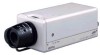
CONNECTION/INSTALLATION Procedures Execute connection/installation according to the procedures described below. Turn OFF the power supply to all equipment to be used before making carefully. 4.Setting the switches (੬ Page 10) 6.Back focus adjustment (੬ Page 21) Av Pk L H ALC LEVEL SET MENU CAMERA SETUP EXT TERM-OFF INT/GL DUPLEX RX TERM-OFF IOT USED ON LL SIMPLEX ON VIDEO DC 7.Auto white balance control adjustment (੬ Page 22) 5.Lens adjustment (੬ Page 20) 3.Mounting the camera 1.Mounting the lens (੬ Page 18) (੬ Page 15) To controlling systems such as RM-P2580 2.Connections (੬ Page 16) DC 12V/AC 24V power supply + - 1 2 DC12V AC24V CLASS 2 ONLY(U TYPE) ISOLATED POWER ONLY (E TYPE) Genlock sync signal generator TX+ TX- RX+ RX- AUX GND A B C D SYNC IN VIDEO OUT POWER Y/C OUT SEE INSTRUCTION MANUAL To alarm terminals such as switches Monitor E-14
-
 1
1 -
2
-
3
-
4
-
5
-
6
-
7
-
8
-
 9
9 -
 10
10 -
 11
11 -
 12
12 -
 13
13 -
 14
14 -
 15
15 -
 16
16 -
 17
17 -
 18
18 -
 19
19 -
20
-
21
-
22
-
23
-
24
-
25
-
26
-
27
-
28
-
29
-
30
-
31
-
32
-
33
-
34
-
35
-
36
-
37
-
38
-
39
-
40
-
41
-
42
-
43
-
44
-
45
-
46
-
47
-
48
-
49
-
50
-
51
-
52
-
53
-
54
-
55
-
56
-
57
-
58
-
59
-
60
-
61
-
62
-
63
-
64
-
65
-
66
-
67
-
68
-
69
-
70
-
71
-
72
-
73
-
74
-
75
-
76
-
77
-
78
-
79
-
80
-
81
-
82
-
83
-
84
-
85
-
86
-
87
-
88
-
89
-
90
-
91
-
92
-
93
-
94
-
95
-
96
-
97
-
98
-
99
-
100
-
101
-
102
-
103
-
104
-
105
-
106
-
107
-
108
-
109
-
110
-
111
-
112
-
113
-
114
-
115
-
116
-
117
-
118
-
119
-
120
-
121
-
122
-
123
-
124
-
125
-
126
-
127
-
128
-
129
-
130
-
131
-
132
-
133
-
134
-
135
-
136
-
137
-
138
-
139
-
140
-
141
-
142
-
143
-
144
-
145
-
146
-
147
-
148
-
149
-
150
-
151
-
152
-
153
-
154
-
155
-
156
-
157
-
158
-
159
-
160
-
161
-
162
-
163
-
164
-
165
-
166
-
167
-
168
-
169
-
170
-
171
-
172
-
173
-
174
-
175
-
176
-
177
-
178
-
179
-
180
-
181
-
182
-
183
-
184
-
185
-
186
-
187
-
188
-
189
-
190
-
191
-
192
-
193
-
194
-
195
-
196
-
197
-
198
-
199
-
200
-
201
-
202
-
203
-
204
-
205
-
206
-
207
-
208
-
209
-
210
-
211
-
212
 |
 |
