JVC TK-C1460U Instruction Manual - Page 8
Controls, Connectors and Indicators, hole 1/4 -20UNC
 |
View all JVC TK-C1460U manuals
Add to My Manuals
Save this manual to your list of manuals |
Page 8 highlights
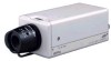
INTRODUCTION Controls, Connectors and Indicators 2 1 3 4 5 7 6 1 Lens mount This means to attach the lens. This is applicable to both the C-mount lenses and CS-mount lenses. 2 Back focus adjustment ring Adjusting the back focus during lens installation. When readjustment is required, loosen the locking screw 3 by turning it counterclockwise and turn the back focus adjustment ring 2 . After the adjustment, tighten the locking screw 3 again. 3 [BF LOCK] Back focus locking screw This serves to fix the back focus-adjusting ring. 4 Camera-mounting bracket The bracket has been attached on the bottom of the camera before shipment. It can also be attached on the top according to the circumstance. To re-attach the bracket use the threaded holes at the top, with the camera mounting bracket fixing screws 7 . 5 Camera-mounting screw hole (1/4 -20UNC) Use this hole when mounting the camera onto a fixer, pan/ MAX. tilt unit, and the like. (Use a 7mm screw shorter than 7 mm.) 6 Rotation-preventive hole Make use of this rotation-preventive hole to prevent any fall when mounting the camera. Make sure that the camera is securely mounted. 7 Camera mounting bracket fixing screws (×2: M2.6 × 6 mm) Be sure to use a 6 mm long screw. E-8
-
 1
1 -
2
-
 3
3 -
 4
4 -
 5
5 -
 6
6 -
 7
7 -
 8
8 -
 9
9 -
 10
10 -
 11
11 -
 12
12 -
 13
13 -
14
-
15
-
16
-
17
-
18
-
19
-
20
-
21
-
22
-
23
-
24
-
25
-
26
-
27
-
28
-
29
-
30
-
31
-
32
-
33
-
34
-
35
-
36
-
37
-
38
-
39
-
40
-
41
-
42
-
43
-
44
-
45
-
46
-
47
-
48
-
49
-
50
-
51
-
52
-
53
-
54
-
55
-
56
-
57
-
58
-
59
-
60
-
61
-
62
-
63
-
64
-
65
-
66
-
67
-
68
-
69
-
70
-
71
-
72
-
73
-
74
-
75
-
76
-
77
-
78
-
79
-
80
-
81
-
82
-
83
-
84
-
85
-
86
-
87
-
88
-
89
-
90
-
91
-
92
-
93
-
94
-
95
-
96
-
97
-
98
-
99
-
100
-
101
-
102
-
103
-
104
-
105
-
106
-
107
-
108
-
109
-
110
-
111
-
112
-
113
-
114
-
115
-
116
-
117
-
118
-
119
-
120
-
121
-
122
-
123
-
124
-
125
-
126
-
127
-
128
-
129
-
130
-
131
-
132
-
133
-
134
-
135
-
136
-
137
-
138
-
139
-
140
-
141
-
142
-
143
-
144
-
145
-
146
-
147
-
148
-
149
-
150
-
151
-
152
-
153
-
154
-
155
-
156
-
157
-
158
-
159
-
160
-
161
-
162
-
163
-
164
-
165
-
166
-
167
-
168
-
169
-
170
-
171
-
172
-
173
-
174
-
175
-
176
-
177
-
178
-
179
-
180
-
181
-
182
-
183
-
184
-
185
-
186
-
187
-
188
-
189
-
190
-
191
-
192
-
193
-
194
-
195
-
196
-
197
-
198
-
199
-
200
-
201
-
202
-
203
-
204
-
205
-
206
-
207
-
208
-
209
-
210
-
211
-
212
 |
 |
