Kenmore 7754 Installation Instructions
Kenmore 7754 - Elite 30 in. Gas Range Manual
 |
View all Kenmore 7754 manuals
Add to My Manuals
Save this manual to your list of manuals |
Kenmore 7754 manual content summary:
- Kenmore 7754 | Installation Instructions - Page 1
installer, service agency or the gas supplier. OVERALL DiMENSiONS Refer to your serial plate for applicable agency certification • ALL RANGES CAN TiP • INJURYTO PERSONS COULD RESULT • iNSTALL ANTI=TIP DEVICE PACKED WiTH RANGE • SEE iNSTALLATiON iNSTRUCTiONS Note: For appliances installed in - Kenmore 7754 | Installation Instructions - Page 2
the oven. Wipe up excess spillage. Follow the cleaning instructions in the Use & Care Guide. . Unlike the standard gas range, THiS COOKTOP IS NOT REMOVABLE. Do not attempt to remove the cooktop. Special instructions for appliances installed in the State of Massachusetts: This appfiance can only - Kenmore 7754 | Installation Instructions - Page 3
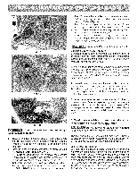
NPT x 3/4" or 1/2" I.D.) supplied with the new flexible appliance conduit for connection of the range. Normal Installation Steps 1. Anti-Tip Bracket Installation Instructions Important Safety Warning To reduce the risk of tipping of the appliance, the range must be secured to the floor by properly - Kenmore 7754 | Installation Instructions - Page 4
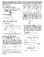
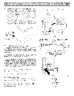
grasp the top rear edge of the range and carefully attempt to titt it forward Manual Shutoff Valve Flare Union / Flexible Flare Union Pressure Appliance Adaptor Regulator Conduit ! 2. Provide an adequate gas supply. This appliance the appliance shall be conducted according to the instructions in - Kenmore 7754 | Installation Instructions - Page 5
appliance conduit (Refer to Fig. 4e). d) Install flare union adapter to external manual shut-offvalve. e) Attach appliance conduit to flare union on shut-off valve. t) Make sure service approximately 1/4," hold tubing down tight least one inch above specified range manifold pressure. The gas supply - Kenmore 7754 | Installation Instructions - Page 6
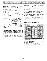
and Surface Burner Grates are installed correctly. Your appliance was shipped with the burner heads and burner caps caps please refer to the Use & Care Guide for more information. Preferred Do Not, Under Burner(some models). 4. 14,200 BTU Power Burner (some models). 5. 3,000 to 18,000 BTU - Kenmore 7754 | Installation Instructions - Page 7
and supply line connectors have been carefully checked for leaks and range has been connected to electric power. The oven burner is equipped with an electric control system as well as an electric oven burner igniter. If your model is equipped with a waist-high broil burner, it will also have an - Kenmore 7754 | Installation Instructions - Page 8
Refer to the Use & Care Manual for cleaning instructions. If removing the range is necessary for cleaning or appliance. Refer to your Use & Care Manual for our toll-free service number and address. Please call or write if you have inquiries about your range product and/or need to order parts. Model - Kenmore 7754 | Installation Instructions - Page 9
se sigue con exactitud la informaci6n que se proporciona en el presente manual, podria producirse fuego o luna explosi6n y causar graves dahos a de la [ parte superior de la cocina. 30" ,----_ NdeO daecaordnnaingyt?an peasrptaecitoraspeorra. debajo de la parte superior Dimensiones y distancias - Kenmore 7754 | Installation Instructions - Page 10
Instrucciones importantes para el instalador 1. Lea todas las instrucciones que se proporcionan en este manual de instalaci6n antes de comenzara instalar la cocina. 2. Retire todo el material de embalaje de los compartimentos del horno antes de conectar el suministro de - Kenmore 7754 | Installation Instructions - Page 11
el lateral de la cocina. Coloque la montura sobre la plantilla y marque la ubicaci6n de los agujeros de los tornillos en la pared. Si la parte posterior de la cocina se encuentra a m&s de 1-1/4" de la pared cuando la instale, deber& fijar la montura al suelo. Para montaje sobre suelo, coloque el - Kenmore 7754 | Installation Instructions - Page 12
de --_ la codna La zona recomendada para la salida de 120V en la parte posterior de la pared y la..zona para la ¢oriexlon a traves de p.ared y v=ilvula de desconexion J Fig. 4a V_lvula de desconexi6n manual Uni6n de campana Conducto flexible Adaptador de uni6n de campana Regulador de - Kenmore 7754 | Installation Instructions - Page 13
en el colector es 4". Fig.4f NO permita que el regulador se mueva sobre la tuberia cuando apriete las conexiones. a. Instale una valvula de cierre manual externa en la tubeda de suministro de gas en una ubicaci6n accesible por fuera de la estufa. Aseg0rese de saber d6nde y c6mo cerrar el suministro - Kenmore 7754 | Installation Instructions - Page 14
LEACONDETENIIVilENPTaOr.asuseguridad personael,steproductodebeserdebidamenctoenectadaouna tomadetierra. 6. Montaje de las Cabezas de los Quemadores Superiores, de las Tapas de los Quemadores de las Rejillas de los Quemadores: y Instruccionesparala tomadetierra Es muy importante asegurarse de que - Kenmore 7754 | Installation Instructions - Page 15
7. Funcionamiento de los Controles Superiores del Gas: Coloque el utensilio de cocina sobre el quemador superior.. Oprima la perilla de control superior y girela a la izquierda para sacarla de la posici6n 'OFF'. (Ver Fig. 1). a. Suelte la perilla y gire a la posici6n "LITE". Nota: Los cuatro - Kenmore 7754 | Installation Instructions - Page 16
del obturador de aire. Para ajustar un tornillo de cierre flojo (vea el grAfico "3" de abajo), vuelva a colocar el obturador de aire, y AI solicitar las partes o realizar pedidos sobre su cocina, siempre asegQrese de incluir el nQmero de modelo y de serie y un nQmero o letra de Iote de la placa de
-
 1
1 -
 2
2 -
 3
3 -
 4
4 -
 5
5 -
 6
6 -
 7
7 -
8
-
9
-
10
-
11
-
12
-
13
-
14
-
15
-
16
 |
 |

iNSTALLATiON
AND
SERVICE
MUST
BE PERFORMED
BY A QUALiFiED
iNSTALLER.
iMPORTANT:
SAVE
FOR
LOCAL
ELECTRICAL
INSPECTOR'S
USE.
READ
AND
SAVE
THESE
iNSTRUCTiONS
FOR
FUTURE
REFERENCE.
if
the
information
in
this
manual
is
not followed
exactly,
a
fire
or
explosion
may
result
causing
property
damage,
personal
injury
or death.
FOR YOUR
SAFETY:
=
Do
not store
or use
gasoline
or other flammable
vapors
and
liquids
in
the
vicinity
of
this
or
any
other
appliance.
=
WHAT
TO DO iF YOU
SMELL
GAS:
•
Do not try
to
light
any appliance.
•
Do
nottouch
any
electrical
switch;
do
not
use
any
phone
in your
building.
•
Immediately
call
your
gas
supplier
from
a neighbor's
phone.
Follow
the
gas supplier's
instructions.
•
if you
cannot
reach
your
gas
supplier,
call
the
fire
department.
=
Installation
and service
must
be performed
by
a
qualified
installer,
service
agency
or
the gas
supplier.
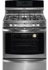
Refer to your serial plate for
applicable agency certification
• ALL
RANGES
CAN
TiP
•
INJURYTO
PERSONS
COULD
RESULT
• iNSTALL
ANTI=TIP
DEVICE
PACKED
WiTH
RANGE
• SEE iNSTALLATiON
iNSTRUCTiONS
Note:
For
appliances
installed
in the
State
of Massachusetts
see page
2.
OVERALL
DiMENSiONS
FRONT
47-3/4"
Side of
"5"-_
Maximum
36=+1/8"
Range 5"
_1-==
30,, _
*Minimum to --
30"
Side Wall
Minimum
t
Minimum to
1÷13"-_1
li
Cabinets on
Maximum Depth
on Either
_
" Either Side
for Cabinets
of Range.
Above Range Top.
_---25"_
30"
----_1
0" Clearance
Below Cooking
Top and at Rear of Range,
Clearances
and
Dimensions
1.
Location--Check
location
where
the
range
will
be
installed.
Check for
proper
electrical
and gas supply,
and the stability
of the floor.
2.
Dimensions
that
are shown
must
be
used.
Given
dimensions
provide
minimum
clearance.
Contact
surface
must
be solid
and level.
Provide
Proper
Fuel
Type
Before Proceeding:
Your appliance was preset at the factory
to operate on Natural Gas only.
Note:
For operation
at elevations
above
2000 ft., appliance
rating
shall
be reduced
at the rate of 4
percent
for each
1000 ft. above
sea level.
p/n 316259347(0807)
1