Kenmore 7754 Installation Instructions - Page 5
Read these, electrical, details, first, connect, electricity, to appliance. - tube
 |
View all Kenmore 7754 manuals
Add to My Manuals
Save this manual to your list of manuals |
Page 5 highlights
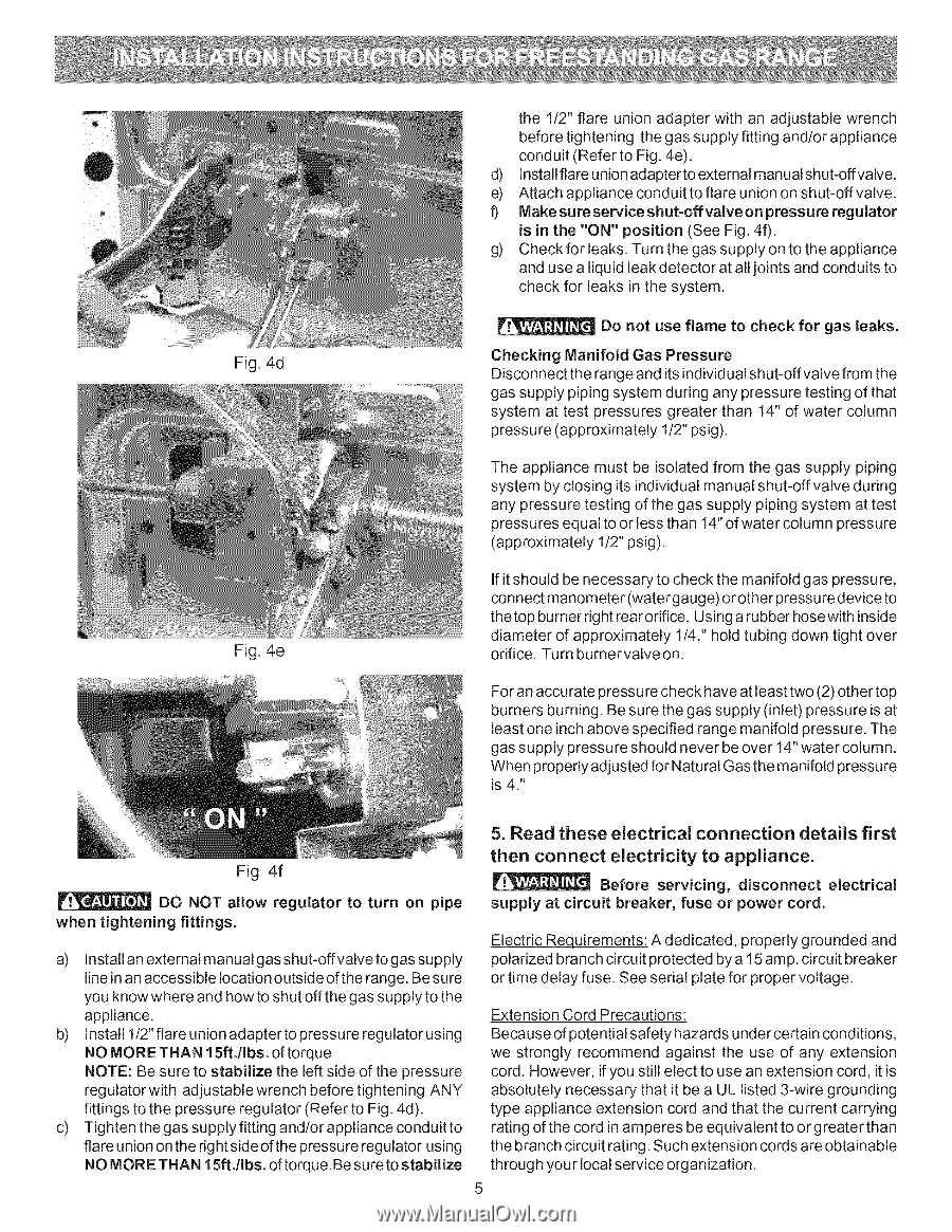
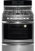
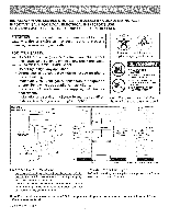
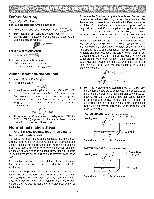
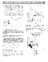
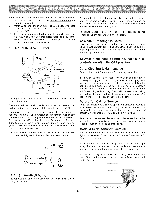
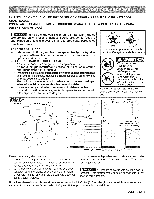
Fig. 4d Fig. 4e the 1/2" flare union adapter with an adjustable wrench before tightening the gas supply fitting and/or appliance conduit (Refer to Fig. 4e). d) Install flare union adapter to external manual shut-offvalve. e) Attach appliance conduit to flare union on shut-off valve. t) Make sure service shut=offvalve on pressure regulator is in the "ON" position (See Fig. 40. g) Check for leaks. Turn the gas supply on to the appliance and use a liquid leak detector at all joints and conduits to check for leaks in the system. Do not use flame to check for gas leaks. Checking Manifold Gas Pressure Disconnect the range and its individual shut-offvalve from the gas supply piping system during any pressure testing of that system at test pressures greater than 14" of water column pressure (approximately 1/2" psig). The appliance must be isolated from the gas supply piping system by closing its individual manual shut-off valve during any pressure testing of the gas supply piping system at test pressures equal to or less than 14" of water column pressure (approximately 1/2" psig). If it should be necessary to check the manifold gas pressure, connect manometer (water gauge) or other pressure device to thetop burner right rear orifice. Using a rubber hosewith inside diameter of approximately 1/4," hold tubing down tight over orifice. Turn burnervalveon. For an accurate pressu re check have at least two (2) other top burners burning. Be sure the gas supply (inlet) pressure is at least one inch above specified range manifold pressure. The gas supply pressure should never be over 14" water column. When properly adjusted for Natural Gas the manifold pressure is 4." 5. Read these electrical connection details first Fig. 4f DO NOT allow regulator to turn on pipe when tightening fittings. a) Install an external manual gas shut-offvalve to gas supply line in an accessible location outside of the range. Be sure you know where and how to shut off the gas supply to the appliance. b) Install l/2"flareunionadaptertopressureregulatorusing NO MORE THAN 15ft./Ibs. of torque NOTE: Be sure to stabilize the left side of the pressure regulatorwith adjustablewrench before tightening ANY fittings to the pressure regulator (Refer to Fig. 4d). c) Tighten the gas supply fitting and/or appliance conduit to flare union on the right sideofthe pressure regulator using NO MORE THAN 15ft./Ibs. of torque. Be sure to stabilize then connect electricity to appliance. Before servicing, disconnect electrical supply at circuit breaker, fuse or power cord. Electric Requirements: A dedicated, properly grounded and polarized branch circuit protected by a 15 amp. circuit breaker or time delay fuse. See serial plate for proper voltage. Extension Cord Precautions: Because of potential safety hazards under certain conditions, we strongly recommend against the use of any extension cord. However, if you still elect to use an extension cord, it is absolutely necessary that it be a UL listed 3-wire grounding type appliance extension cord and that the current carrying rating of the cord in amperes be equivalent to or greater than the branch circuit rating. Such extension cords are obtainable through your local service organization. 5
-
 1
1 -
 2
2 -
 3
3 -
 4
4 -
 5
5 -
 6
6 -
 7
7 -
 8
8 -
 9
9 -
 10
10 -
 11
11 -
12
-
13
-
14
-
15
-
16
 |
 |