LG H20J55DT Owner's Manual - Page 15
Pillow Speaker Setup
 |
View all LG H20J55DT manuals
Add to My Manuals
Save this manual to your list of manuals |
Page 15 highlights
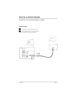
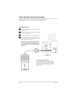
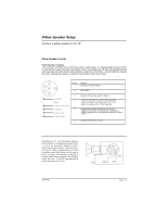
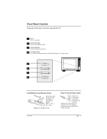
Pillow Speaker Setup Connect a pillow speaker to the TV Pillow Speaker Control Pillow Speaker Interface This connector furnishes three control lines and an audio output. A patient-pendant remote control, or entertainment audio and nurse call system may be connected here. All lines are isolated from the AC power line and earth ground. (Opto-isolators isolate the control lines, and a transformer isolates the audio. There are no relays or inductive components in the control lines.) 4 5 6 1 2 1 2 3 4 5 6 Pin No. 1 Purpose External TV On/Off switch. 3 2 (Not used.) 3 TV ON/OFF 4 OPEN CHAN UP/DATA IN COMMON 5 AUDIO OUT CHAN DOWN 6 External Channel Up switch or Data in. Common connection for control, data, and audio output. Impedance to earth ground is a 10-meg resistor in parallel with a 1100 pf capacitor. Isolated audio output. Nominal 14-ohm source impedance with short circuit protection. Intended for a pillow speaker with a low-impedance pad-type volume control. External Channel Down switch. Controlling the TV with Mechanical Switches Pin 4 (common) is momentarily connected to pin 1, 3, or 6 via push-action switches to control On/Off and Channel Up/Down. These pins are at +13 volts DC (when measured from pin 4) with the switches open. Current draw is 8 mA when a switch is closed. (This operation is identical to previous Zenith models using the 5-Wire Interface except that only +7 volts DC was supplied and current draw was only 2.5 mA.) SPKR. VOLUME CONTROL TV ON/OFF CHAN DOWN 4 5 6 1 2 3 (MALE PLUG) CHAN UP 206-4065 Page 15
-
 1
1 -
2
-
3
-
4
-
5
-
6
-
7
-
8
-
9
-
 10
10 -
 11
11 -
 12
12 -
 13
13 -
 14
14 -
 15
15 -
 16
16 -
 17
17 -
 18
18 -
 19
19 -
 20
20 -
21
-
22
-
23
-
24
-
25
-
26
-
27
-
28
-
29
-
30
-
31
-
32
-
33
-
34
-
35
-
36
-
37
-
38
-
39
-
40
-
41
-
42
-
43
-
44
-
45
-
46
-
47
-
48
-
49
-
50
-
51
-
52
-
53
-
54
-
55
-
56
-
57
-
58
-
59
-
60
-
61
-
62
-
63
-
64
 |
 |
