LG LFX28968SW Service Manual - Page 7
Defrost Control Assembly, Door Alignment, Fan And Fan Motorevaporator - manual
 |
View all LG LFX28968SW manuals
Add to My Manuals
Save this manual to your list of manuals |
Page 7 highlights
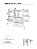
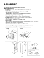
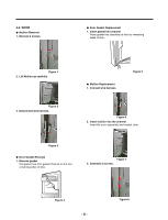
3-3 Door Alignment If the space between the door are uneven, follow the instructions to align them. Remove the Base Grillie. Turn the leveling legs counter clock wise to raise or clock wise to lower the height of the front of the refrigerator by using flat blade screw driver or 11/32" wrench. Use the wrench (Included with the User Manual) to adjust the bolt in the door hinge to adjust the height. (CCW to raise or CW to lower the height.) * Ice Fan Scroll Assembly Replacement 1) Remove the plastic guide on the left side, using a phillips screwdriver to remove the screws. 2) Pull off the sensor cover. 3) Remove the grill cover. 4) Gently pull on the grill assembly to remove. 5) Disconnect the wiring harness. 6) Remove all screws on the scroll assembly. (1) (2) (3) (4) Figure 9 3-4 FAN AND FAN MOTOR(EVAPORATOR) 1. Remove the freezer drawer. (If your refrigerator has an icemaker, remove the icemaker first) 2. Remove the plastic guide for slides on left side by unscrewing phillips head screws. 3. Remove the grille by removing 4 screws and pulling the grille forward. 4. Remove the Fan Motor assembly by loosening 3 screws and disassembling the shroud. 5. Pull out the fan and separate the Fan Motor and Bracket. FAN MOTOR Shroud (5) (6) Figure 11 3-5 DEFROST CONTROL ASSEMBLY Defrost Control assembly consists of Defrost Sensor and FUSE-M. The Defrost Sensor works to defrost automatically. It is attached to the metal side of the Evaporator and senses its temperature. At 46F(8°C), it turns the Defrost Heater off. Fuse-M is a safety device for preventing over-heating of the Heater when defrosting. 1. Pull out the grille assembly. (Figure 12) 2. Separate the connector with the Defrost Control assembly and replace the Defrost Control assembly after cutting the Tie Wrap. (Figure 13) GRILLE ASSEMBLY DEFROST-CONTROL ASSEMBLY BRACKET MOTOR Figure 10 - 7- Figure 12 Figure 13
-
 1
1 -
 2
2 -
 3
3 -
 4
4 -
 5
5 -
 6
6 -
 7
7 -
 8
8 -
 9
9 -
 10
10 -
 11
11 -
 12
12 -
13
-
14
-
15
-
16
-
17
-
18
-
19
-
20
-
21
-
22
-
23
-
24
-
25
-
26
-
27
-
28
-
29
-
30
-
31
-
32
-
33
-
34
-
35
-
36
-
37
-
38
-
39
-
40
-
41
-
42
-
43
-
44
-
45
-
46
-
47
-
48
-
49
-
50
-
51
-
52
-
53
-
54
-
55
-
56
-
57
-
58
-
59
-
60
-
61
-
62
-
63
-
64
-
65
-
66
-
67
-
68
-
69
-
70
-
71
-
72
-
73
-
74
-
75
-
76
-
77
-
78
-
79
-
80
-
81
-
82
 |
 |
