Lenovo ThinkPad X30 ThinkPad X30, X31, X32 - Hardware Maintenance Manual - Page 92
installing, Cable, routing, 11b/modem, combo
 |
View all Lenovo ThinkPad X30 manuals
Add to My Manuals
Save this manual to your list of manuals |
Page 92 highlights
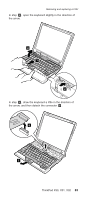
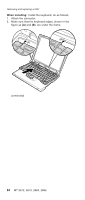
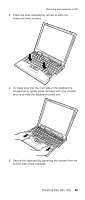
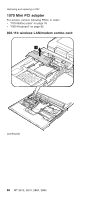
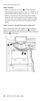
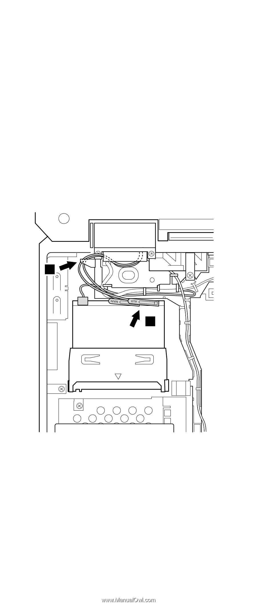
Removing and replacing a FRU When installing: v Make sure that the connector 5 is firmly attached. v Plug the gray antenna cable into jack J1, or MAIN, or M, and the black antenna cable into jack J2, or AUX, or A. v With the notched end of the card toward the socket, insert the card into the socket, and then press it firmly. Pivot the card until it snaps into place. Make sure that the card is firmly fixed in the slot and does not move easily. Cable routing for the 802.11b/modem combo card When attaching the Mini PCI adapter, route the antenna cables to go under the cable guide as in a , and if the antenna cable has the tab, place the each tab as indicated by arrow b in this figure. a b 88 MT 2672, 2673, 2884, 2885
-
 1
1 -
2
-
3
-
4
-
5
-
6
-
7
-
8
-
9
-
10
-
11
-
12
-
13
-
14
-
15
-
16
-
17
-
18
-
19
-
20
-
21
-
22
-
23
-
24
-
25
-
26
-
27
-
28
-
29
-
30
-
31
-
32
-
33
-
34
-
35
-
36
-
37
-
38
-
39
-
40
-
41
-
42
-
43
-
44
-
45
-
46
-
47
-
48
-
49
-
50
-
51
-
52
-
53
-
54
-
55
-
56
-
57
-
58
-
59
-
60
-
61
-
62
-
63
-
64
-
65
-
66
-
67
-
68
-
69
-
70
-
71
-
72
-
73
-
74
-
75
-
76
-
77
-
78
-
79
-
80
-
81
-
82
-
83
-
84
-
85
-
86
-
 87
87 -
 88
88 -
 89
89 -
 90
90 -
 91
91 -
 92
92 -
 93
93 -
 94
94 -
 95
95 -
 96
96 -
 97
97 -
98
-
99
-
100
-
101
-
102
-
103
-
104
-
105
-
106
-
107
-
108
-
109
-
110
-
111
-
112
-
113
-
114
-
115
-
116
-
117
-
118
-
119
-
120
-
121
-
122
-
123
-
124
-
125
-
126
-
127
-
128
-
129
-
130
-
131
-
132
-
133
-
134
-
135
-
136
-
137
-
138
-
139
-
140
-
141
-
142
-
143
-
144
-
145
-
146
-
147
-
148
-
149
-
150
-
151
-
152
-
153
-
154
-
155
-
156
-
157
-
158
-
159
-
160
-
161
-
162
-
163
-
164
-
165
-
166
-
167
-
168
-
169
-
170
-
171
-
172
-
173
-
174
-
175
-
176
-
177
-
178
-
179
-
180
-
181
-
182
-
183
-
184
-
185
-
186
-
187
-
188
-
189
-
190
-
191
-
192
-
193
-
194
-
195
-
196
 |
 |
When
installing:
v
Make
sure
that
the
connector
±5²
is
firmly
attached.
v
Plug
the
gray
antenna
cable
into
jack
J1
,
or
MAIN
,
or
M
,
and
the
black
antenna
cable
into
jack
J2
,
or
AUX
,
or
A
.
v
With
the
notched
end
of
the
card
toward
the
socket,
insert
the
card
into
the
socket,
and
then
press
it
firmly.
Pivot
the
card
until
it
snaps
into
place.
Make
sure
that
the
card
is
firmly
fixed
in
the
slot
and
does
not
move
easily.
Cable
routing
for
the
802.11b/modem
combo
card
When
attaching
the
Mini
PCI
adapter,
route
the
antenna
cables
to
go
under
the
cable
guide
as
in
±a²
,
and
if
the
antenna
cable
has
the
tab,
place
the
each
tab
as
indicated
by
arrow
±b²
in
this
figure.
a
b
Removing
and
replacing
a
FRU
88
MT
2672,
2673,
2884,
2885